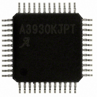
A3930KJPTR-T Allegro Microsystems Inc, A3930KJPTR-T Datasheet - Page 15

A3930KJPTR-T
Manufacturer Part Number
A3930KJPTR-T
Description
IC,Motor Controller,QFP,48PIN
Manufacturer
Allegro Microsystems Inc
Datasheet
1.A3930KJPTR-T.pdf
(21 pages)
Specifications of A3930KJPTR-T
Applications
DC Motor Controller, Brushless (BLDC), 3 Phase
Number Of Outputs
1
Current - Output
500mA
Voltage - Supply
5.5 V ~ 50 V
Operating Temperature
-40°C ~ 150°C
Mounting Type
Surface Mount
Package / Case
48-LFQFP Exposed Pad
Lead Free Status / RoHS Status
Lead free / RoHS Compliant
Voltage - Load
-
Lead Free Status / RoHS Status
Lead free / RoHS Compliant
Other names
620-1289-2
A3930KJPTR-T
A3930KJPTR-T
Available stocks
Company
Part Number
Manufacturer
Quantity
Price
Company:
Part Number:
A3930KJPTR-T
Manufacturer:
ALLEGRO
Quantity:
1 001
Company:
Part Number:
A3930KJPTR-T
Manufacturer:
Allegro MicroSystems, LLC
Quantity:
10 000
Part Number:
A3930KJPTR-T
Manufacturer:
ALLEGRO/雅丽高
Quantity:
20 000
A3930
A3931
high-side PWM cycle is requested. The minimum time required
to charge the capacitor is approximated by:
At power-on, and when the drivers have been disabled for a long
time, the CBOOT may be completely discharged. In these cases,
ΔV can be considered to be the full high-side drive voltage,
12 V. Otherwise, ΔV is the amount of voltage dropped during the
charge transfer, which should be 400 mV or less. The capacitor is
charged whenever the Sx pin is pulled low via a GLx PWM cycle,
and current flows from VREG through the internal bootstrap
diode circuit to CBOOT.
Bootstrap Charge Monitor The A3930 and A3931 provide
automatic bootstrap capacitor charge management. The boot-
strap capacitor voltage for each phase, V
checked to ensure that it is above the bootstrap undervoltage
threshold, V
A3930 and A3931 will turn on the necessary low-side FET until
the V
The minimum charge time is typically 7 μs, but may be longer for
very large values of the bootstrap capacitor (C
V
an undervoltage fault will be flagged, as shown in table 1.
PWM Control
The A3930 and A3931 have the flexibility to be used in many
different motor control schemes. The internal PWM control can
be used to provide fully integrated, closed-loop current control.
Alternatively, current-mode or voltage-mode control are possible
using external control circuits with either the DIR or the PWM
input pins.
Internal PWM Control The internal PWM current control
function is useful in applications where motor torque control
or simple maximum current limitation is required. However,
for motor speed control applications, it is usually better to use
external PWM control either as a closed- or open-loop system.
External PWM Control When external PWM control is used, it
is possible to completely disable the internal PWM control circuit
by connecting the RC pin to AGND.
With the internal control disabled, however, care should be taken
to avoid excessive current in the power FETs because the A3930/
BOOT
BOOT
does not exceed V
exceeds V
t
CHARGE(min)
BOOTUV
and
. If V
BOOTUV
≈ C
BOOT
BOOTUV
BOOT
plus the hysteresis, V
drops below this threshold, the
× ΔV /250 mA
within approximately 200 μs,
BOOTx
BOOT
, is continuously
BOOTUVHys
>1000 nF). If
Automotive 3-Phase BLDC Controller
.
A3931 will not limit the current. Short-circuit detection will still
be available in case of faults. The output of the sense amplifier is
also available, but provision must be made in the external control
circuits to ignore (blank) the transients at the switching points.
External and Internal Combined PWM Control Where
external PWM control is used but current limitation is still
required, internal PWM current control can be used at the
same time as external PWM control. To do so, usually the
internal PWM frequency is set lower than the external PWM
frequency. This allows the external PWM signal to dominate and
synchronize the internal PWM circuit. It does this by discharging
the timing capacitor, CT, when the PWM pin is low. When
internal and external PWM control are used together, all control
features of the A3930/A3931 are available and active, including:
dead time, current comparator, and comparator blanking.
PWM Frequency Should be set high enough to avoid any
audible noise, but low enough to ensure adequate charging of the
boot capacitor, CBOOT. The external resistor RT and capacitor
CT, connected in parallel from the RC pin to AGND, set the
PWM frequency to approximately:
R
PWM Blank The timing capacitor, CT, also serves as the
means to set the blank time duration. t
PWM off-cycle, a high-side gate selected by the commutation
logic turns on. At this time, large current transients can occur
during the reverse recovery time of the intrinsic source drain
body diodes of the external power MOSFETs. To prevent false
tripping of the current-sense comparator, the output of the current
comparator is ignored during the blank time.
The length of t
PWM. It is set by the value of the timing capacitor, CT, according
to the following formulas:
for internal PWM: t
for external PWM: t
A nominal C
for external PWM and 860 ns for internal PWM. The user must
ensure that C
T
should be in the range of 5 to 400 kΩ.
T
T
value of 680 pF will give a blanking time of 1.3 μs
BLANK
is large enough to cover the current-spike duration.
f
OSC
BLANK
≈ 1 / (R
BLANK
is different for internal versus external
and MOSFET Driver
T
(μs) = 1260 × C
(μs) = 2000 × C
115 Northeast Cutoff
1.508.853.5000; www.allegromicro.com
Allegro MicroSystems, Inc.
Worcester, Massachusetts 01615-0036 U.S.A.
C
T
+ t
BLANK
BLANK
+ t
T
T
DEAD
. At the end of the
(μF), and
(μF) .
) .
15


