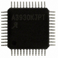
A3930KJPTR-T Allegro Microsystems Inc, A3930KJPTR-T Datasheet - Page 6

A3930KJPTR-T
Manufacturer Part Number
A3930KJPTR-T
Description
IC,Motor Controller,QFP,48PIN
Manufacturer
Allegro Microsystems Inc
Datasheet
1.A3930KJPTR-T.pdf
(21 pages)
Specifications of A3930KJPTR-T
Applications
DC Motor Controller, Brushless (BLDC), 3 Phase
Number Of Outputs
1
Current - Output
500mA
Voltage - Supply
5.5 V ~ 50 V
Operating Temperature
-40°C ~ 150°C
Mounting Type
Surface Mount
Package / Case
48-LFQFP Exposed Pad
Lead Free Status / RoHS Status
Lead free / RoHS Compliant
Voltage - Load
-
Lead Free Status / RoHS Status
Lead free / RoHS Compliant
Other names
620-1289-2
A3930KJPTR-T
A3930KJPTR-T
Available stocks
Company
Part Number
Manufacturer
Quantity
Price
Company:
Part Number:
A3930KJPTR-T
Manufacturer:
ALLEGRO
Quantity:
1 001
Company:
Part Number:
A3930KJPTR-T
Manufacturer:
Allegro MicroSystems, LLC
Quantity:
10 000
Part Number:
A3930KJPTR-T
Manufacturer:
ALLEGRO/雅丽高
Quantity:
20 000
A3930
A3931
ELECTRICAL CHARACTERISTICS (continued)
Supply Rejection
Small Signal 3 dB Bandwidth Frequency
Settling Time
AC Common Mode Gain
Common Mode Recovery Time
Output Slew Rate
Input Overload Recovery Time
Current Limit
Reference Comparator Input Offset Voltage
Reference Input Clamp Voltage
Comparator Blank Time
REF Input Bias Current
RC Charge Current
RC HIgh Voltage Threshold
RC Low Voltage Threshold
Protection
VREG Undervoltage Lockout
Bootstrap Capacitor Undervoltage Lockout
Bootstrap Capacitor Undervoltage Lockout
Hysteresis
V5 Undervoltage Lockout
V5 Undervoltage Lockout Hysteresis
VDSTH Input Voltage Range
VDSTH Input Current
VDRAIN Input Voltage Range
Short-to-Ground Threshold Offset
Short-to-Battery Threshold Offset
Low Load Current Detection Voltage
Overtemperature Flag
Overtemperature Flag Hysteresis
1
2
3
4
5
6
Parameters are tested at 135C. Values at 150C are guaranteed by design or correlation.
For input and output current specifications, negative current is defined as coming out of (sourcing) the specified device pin.
High side on. As V
Low side on. As V
V
Function is correct but parameters not guaranteed above or below general limits (7 to 45 V).
STG
threshold is V
Characteristics
and
SX
SX
DTSTH
increases, fault occurs if V
2
decreases, fault occurs if V
2
+ V
STGO
. V
4,5
STB
3,5
threshold is V
SX
BAT
V
– V
BOOTUVHys
V
Symbol
– V
V
V
t
V
PSRR
V
V
V
V
V
T
SETTLE
A
t
I
LSS
t
BOOTUV
I
V
V
V
IDREC
V
REGUV
5UVHys
CMrec
IBREF
DTSTH
DSTH
f
DRAIN
STGO
T
JFHys
SR
REFC
t
I
DSTH
STBO
CSOL
CMac
3dB
RCH
RC
RCL
5UV
SX
IOC
RC
JF
> V
> V
+ V
STB
at T
STG
STBO
.
CSP = CSN = AGND, 0 to 300 kHz
V
To within 10%, V
wave
V
To within 100 mV, V
step
10% to 90% points, V
step
To within 10%, V
External pull-up to 5 V R
R
V
V
V
V
V
V
V
V
V
Temperature increasing
Recovery = T
J
.
= –40°C to 150°C, V
ID
ICR
REG
REG
BOOT
BOOTUVHys
5
DSTH
DSTH
DSTH
DSTH
T
Automotive 3-Phase BLDC Controller
= 56 kΩ, C
.
=10 mV
falling
= 250 mV
rising
falling
> 1 V
≤ 1 V, 7 V ≤ V
> 1 V
≤ 1 V, 7 V ≤ V
falling, V
PP
Test Conditions
= %V
T
JF
PP
= 470 pF
Cx
, 0 to 1 MHz
– T
CSOUT
ID
REG
– V
=250 mV to 0 V step
ICR
JFHys
DRAIN
DRAIN
ID
Sx
BB
= +4.1 to 0 V
= 1 V
= 0 to 175 mV
REF
= 7 to 45 V, unless otherwise noted
≤ 30 V
≤ 30 V
PP
= 200 kΩ
square
and MOSFET Driver
115 Northeast Cutoff
1.508.853.5000; www.allegromicro.com
Allegro MicroSystems, Inc.
Worcester, Massachusetts 01615-0036 U.S.A.
–1.15
–150
–150
Min.
3.75
6.75
–15
300
1.7
0.6
7.5
3.4
0.3
59
–1
–
–
–
–
–
–
–
–
–
–
7
–
–
–
–
–
±300
±300
Typ.
7.25
3.65
400
–28
500
650
400
V
500
170
1.6
1.9
0.7
45
20
–1
13
15
1
0
4
0
8
–
–
–
–
–
BB
1
–0.85
Max.
7.75
500
150
150
4.2
2.1
0.8
8.5
4.0
15
69
45
–
–
–
–
–
–
–
–
–
–
4
1
–
–
–
–
–
Units
MHz
V/μs
mV
mV
mV
mV
mV
mV
mV
mA
dB
dB
μA
μA
ºC
ns
μs
ns
ns
ºC
%
%
V
V
V
V
V
V
V
V
6


