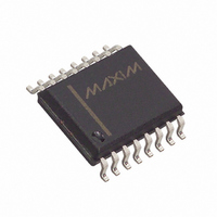
MAX187BCWE+ Maxim Integrated Products, MAX187BCWE+ Datasheet - Page 14

MAX187BCWE+
Manufacturer Part Number
MAX187BCWE+
Description
IC ADC SRL12BIT 5V 75KSPS 16SOIC
Manufacturer
Maxim Integrated Products
Datasheet
1.MAX189CCPA.pdf
(20 pages)
Specifications of MAX187BCWE+
Number Of Bits
12
Sampling Rate (per Second)
75k
Data Interface
MICROWIRE™, QSPI™, Serial, SPI™
Number Of Converters
1
Power Dissipation (max)
478mW
Voltage Supply Source
Single Supply
Operating Temperature
0°C ~ 70°C
Mounting Type
Surface Mount
Package / Case
16-SOIC (0.300", 7.50mm Width)
Number Of Adc Inputs
1
Architecture
SAR
Conversion Rate
75 KSPs
Resolution
12 bit
Input Type
Voltage
Interface Type
Serial
Voltage Reference
Internal 4.096 V
Supply Voltage (max)
5 V
Maximum Power Dissipation
478 mW
Maximum Operating Temperature
+ 70 C
Mounting Style
SMD/SMT
Minimum Operating Temperature
0 C
Lead Free Status / RoHS Status
Lead free / RoHS Compliant
+5V, Low-Power, 12-Bit Serial ADCs
The effective resolution (effective number of bits) the
ADC provides can be determined by transposing the
above equation and substituting in the measured
SINAD: N = (SINAD - 1.76)/6.02. Figure 12 shows the
effective number of bits as a function of the input fre-
quency for the MAX187/MAX189.
If a pure sine wave is sampled by an ADC at greater
than the Nyquist frequency, the nonlinearities in the
ADC’s transfer function create harmonics of the input
frequency present in the sampled output data.
Total Harmonic Distortion (THD) is the ratio of the RMS
sum of all the harmonics (in the frequency band above
DC and below one-half the sample rate, but not includ-
ing the DC component) to the RMS amplitude of the
fundamental frequency. This is expressed as follows:
where V
through V
harmonics. The THD specification in the Electrical
Characteristics includes the 2nd through 5th
harmonics.
14
Figure 12. Effective Bits vs. Input Frequency
______________________________________________________________________________________
THD = 20log
12.2
12.0
11.8
11.6
11.4
11.2
11.0
10.8
10.6
10.4
10.2
1
N
is the fundamental RMS amplitude, and V
are the amplitudes of the 2nd through Nth
1
√
INPUT FREQUENCY (kHz)
V
Total Harmonic Distortion
10
2
2
+ V
3
2
(UNDERSAMPLED)
+ V
V
1
100
4
2
+ … V
1000
N
2
2
Figure 13. Common Serial-Interface Connections to the
MAX187/MAX189
a. SPI
b. QSPI
c. MICROWIRE
MISO
MISO
SCK
SCK
I/O
SS
CS
SS
I/O
SK
SI
+5V
+5V
CS
SCLK
DOUT
CS
SCLK
DOUT
CS
SCLK
DOUT
MAX187
MAX189
MAX187
MAX189
MAX187
MAX189


