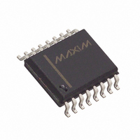
MAX187BCWE+ Maxim Integrated Products, MAX187BCWE+ Datasheet - Page 16

MAX187BCWE+
Manufacturer Part Number
MAX187BCWE+
Description
IC ADC SRL12BIT 5V 75KSPS 16SOIC
Manufacturer
Maxim Integrated Products
Datasheet
1.MAX189CCPA.pdf
(20 pages)
Specifications of MAX187BCWE+
Number Of Bits
12
Sampling Rate (per Second)
75k
Data Interface
MICROWIRE™, QSPI™, Serial, SPI™
Number Of Converters
1
Power Dissipation (max)
478mW
Voltage Supply Source
Single Supply
Operating Temperature
0°C ~ 70°C
Mounting Type
Surface Mount
Package / Case
16-SOIC (0.300", 7.50mm Width)
Number Of Adc Inputs
1
Architecture
SAR
Conversion Rate
75 KSPs
Resolution
12 bit
Input Type
Voltage
Interface Type
Serial
Voltage Reference
Internal 4.096 V
Supply Voltage (max)
5 V
Maximum Power Dissipation
478 mW
Maximum Operating Temperature
+ 70 C
Mounting Style
SMD/SMT
Minimum Operating Temperature
0 C
Lead Free Status / RoHS Status
Lead free / RoHS Compliant
When using SPI or QSPI, set CPOL = 0 and CPHA = 0.
Conversion begins with a CS falling edge. DOUT goes
low, indicating a conversion in progress. Wait until
DOUT goes high or the maximum specified 8.5µs con-
version time. Two consecutive 1-byte reads are
required to get the full 12 bits from the ADC. DOUT out-
put data transitions on SCLK’s falling edge and is
clocked into the µP on SCLK’s rising edge.
The first byte contains a leading 1 and 7 bits of conver-
sion result. The second byte contains the remaining 5
bits and 3 trailing 0s. See Figure 13 for connections
and Figure 14 for timing.
Set CPOL = CPHA = 0. Unlike SPI, which requires two
1-byte reads to acquire the 12 bits of data from the
ADC, QSPI allows the minimum number of clock cycles
necessary to clock in the data. The MAX187/MAX189
require 13 clock cycles from the µP to clock out the
+5V, Low-Power, 12-Bit Serial ADCs
Figure 16. 12-Bit Isolated ADC
16
ANALOG
INPUT
______________________________________________________________________________________
0.1 F
GROUND
SIGNAL
10 F
4.7 F 5
+5V
1
2
4
V DD
AIN
REF
GND
MAX187
BARRIER MUST BE ISOLATED POWER
SHDN
DOUT
SCLK
+5V ON THIS SIDE OF
CS
SPI and Microwire
3
7
8
6
3k
470
3k
QSPI
8
7
6
5
8
7
6
5
1
2
3
4
6N136
6N136
6N136
12 bits of data with no trailing 0s (Figure 15). The maxi-
mum clock frequency to ensure compatibility with QSPI
is 2.77MHz.
Many industrial applications require electrical isolation
to separate the control electronics from hazardous
electrical conditions, provide noise immunity, or pre-
vent excessive current flow where ground disparities
exist between the ADC and the rest of the system.
Isolation amplifiers typically used to accomplish these
tasks are expensive. In cases where the signal is even-
tually converted to a digital form, it is cost effective to
isolate the input using opto-couplers in a serial link.
The MAX187 is ideal in this application because it
includes both T/H amplifier and voltage reference,
operates from a single supply, and consumes very little
power (Figure 16).
1
2
3
4
1
2
3
4
8
7
6
5
200
200
+5V
8.2k
74HC04
74HC04
Serial-to-Parallel Conversion
Opto-Isolated Interface,
+5V
14
11
12
10
14
11
12
10
SER
SCK
RCK
SCLR
SER
SCK
RCK
SCLR
SCLK/INPUT CLOCK
74HC595
74HC595
13
13
QH
9
8
8
CS/START
QH
QG
QD
QC
QB
QA
QH
QG
QD
QC
QB
QA
QF
QE
QF
QE
7
6
5
4
3
2
1
15
16
7
6
5
4
3
2
1
15
16
D11 (MSB)
D10
D9
D8
+5V
D7
D6
D5
D4
D3
D2
D1
D0(LSB)
+5V
0.1 F
0.1 F


