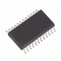
MAX132CWG+ Maxim Integrated Products, MAX132CWG+ Datasheet - Page 11

MAX132CWG+
Manufacturer Part Number
MAX132CWG+
Description
IC ADC 18BIT W/SRL INTRFC 24SOIC
Manufacturer
Maxim Integrated Products
Datasheet
1.MAX132CNG.pdf
(16 pages)
Specifications of MAX132CWG+
Number Of Bits
18
Sampling Rate (per Second)
100
Data Interface
MICROWIRE™, Serial, SPI™
Number Of Converters
1
Voltage Supply Source
Dual ±
Operating Temperature
0°C ~ 70°C
Mounting Type
Surface Mount
Package / Case
24-SOIC (0.300", 7.50mm Width)
Architecture
Dual Slope
Conversion Rate
0.1 KSPs
Input Type
Voltage
Interface Type
4-Wire (SPI, QSPI, MICROWIRE, TMS320)
Supply Voltage (max)
5 V
Maximum Power Dissipation
647 mW
Maximum Operating Temperature
+ 70 C
Mounting Style
SMD/SMT
Minimum Operating Temperature
0 C
Lead Free Status / RoHS Status
Lead free / RoHS Compliant
Averaging 2 or 3 read-zero measurements provides the
most accurate read-zero value. Perform a read-zero
sequence whenever a large change in the input voltage
is expected.
When the sleep bit is set to 1, (bit D5 in command input
register 0), the low-power sleep mode starts when EOC
returns high. In sleep mode, the supply current is typi-
cally 1µA and the oscillator shuts down. The interface
remains active and data can be read. When exiting
sleep mode, the analog circuitry needs time to stabilize
before the next conversion starts. Accomplish this by
writing a dummy instruction to emerge from sleep
mode, and wait at least one conversion cycle before
writing a start instruction.
With a 32,768Hz crystal, the 50Hz/60Hz bit sets the
integrate period equal to one line cycle for 50Hz/60Hz
environments. When D6 (in command input register 0)
is set to 0, the integrate count is an integer multiple of
60Hz (32,768Hz/60Hz = 546 counts). When D6 is set to
1, the integrate input count is an integer multiple of
50Hz (32,768Hz/50Hz = 655 counts). Achieve the
greatest AC rejection by adjusting the integration peri-
od for 50Hz or 60Hz.
Figure 10. Conversion Timing (Negative Input Shown)
RESET
0000
0001
ZERO INT
INTERNAL CONVERSION DATA LATCH
INT OUT
INT START
50Hz mode
60Hz mode
60Hz
0111
655
INTEGRATE
______________________________________________________________________________________
545
CHOP
659 667
±18-Bit ADC with Serial Interface
MAX
545
DE-1
MAX
679
50Hz/60Hz
Sleep Bit
OVERRANGE
(SEE TEXT)
SOFT
AREA
1346
The start conversion bit (D7) in command input register
0 initiates a conversion when set to 1. The MAX132
immediately starts a conversion, stops at conversion
end, and then waits for the next start-bit command. A
start instruction is needed to initiate each conversion.
To initiate a continuous data stream, write a separate
start command for each conversion in three ways:
1) Wait longer than a known conversion time and then
2) Poll either the EOC status register bit or the EOC
3) Set the start bit to 1 before a conversion end. The
X8-1
264
write another start command.
line to determine conversion end and start time for
the next conversion. EOC becomes 1 at conversion
end at count 0000 of the conversion counter (Figure
10).
internal conversion counter is then checked for its
count. If the count is 0000 (EOC = 1), a new conver-
sion starts and the conversion counter is set to
0001. The start bit resets to 0 after 5 clock cycles.
The MAX132 will not check the start bit again until
the conversion counter returns to a 0000 count. This
means a start command can be given any time after
0005 internal conversion count; the next conversion
starts when the counter returns to 0000.
1600
DE-2
38
1638
X8-2
145
1783
DE-3
40
1823
X8-3
147
1970
Start Conversion Bit
DE-4
47
2017
LATCH
ZERO INT
RESET EVENTS
30
2047
EOC
0000
11


