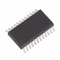
MAX132CWG+ Maxim Integrated Products, MAX132CWG+ Datasheet - Page 9

MAX132CWG+
Manufacturer Part Number
MAX132CWG+
Description
IC ADC 18BIT W/SRL INTRFC 24SOIC
Manufacturer
Maxim Integrated Products
Datasheet
1.MAX132CNG.pdf
(16 pages)
Specifications of MAX132CWG+
Number Of Bits
18
Sampling Rate (per Second)
100
Data Interface
MICROWIRE™, Serial, SPI™
Number Of Converters
1
Voltage Supply Source
Dual ±
Operating Temperature
0°C ~ 70°C
Mounting Type
Surface Mount
Package / Case
24-SOIC (0.300", 7.50mm Width)
Architecture
Dual Slope
Conversion Rate
0.1 KSPs
Input Type
Voltage
Interface Type
4-Wire (SPI, QSPI, MICROWIRE, TMS320)
Supply Voltage (max)
5 V
Maximum Power Dissipation
647 mW
Maximum Operating Temperature
+ 70 C
Mounting Style
SMD/SMT
Minimum Operating Temperature
0 C
Lead Free Status / RoHS Status
Lead free / RoHS Compliant
Note: Capacitor values are for a 3.0V integrator swing.
Manufactures of miniature quartz resonators include:
The integrator resistor sets the maximum integrator out-
put current for the integrate phase. A 602kΩ low-noise,
metal-film integrator resistor is recommended for use
with reference voltages between 545mV and 655mV.
Best linearity is achieved when the integration current
(I
ages, select R
The oscillator frequency, integrator resistor, and inte-
grator capacitor set the maximum integrator output volt-
age swing for full-scale reading. The integrator voltage
swing is about 3V and should not come within 2V of
either supply rail to avoid saturation. A 602kΩ integrator
resistor and a 4.7nF integrator capacitor are recom-
mended with a clock frequency of 32,768Hz. If different
clock frequencies are used, select C
lowing equations:
Table 1. Crystal Frequencies and
Integrator Capacitors for 50Hz to 60Hz
Operation
C
and
Conv/sec
INT
INT
) does not exceed 2.5µA. For other reference volt-
16
32
48
64
80
96
I
R
and
INT
Epson of America
C-2 (through-hole), MC-306 (SMD)
Phone: (310) 787-6300; Fax: (310) 782-5320
(
R
INT
(
V
INT
IN FS
131,072
163,840
196,608
Crystal
98, 304
32,768
65,536
INT
Freq.
(
(Hz)
) (
)
V
as follows:
) (
_______________________________________________________________________________________
V
R
2 5
SWING
REF
.
INT
t
INT
A
C
)
INT
)
4700
2700
1800
1200
1000
(pF)
,
820
/60Hz
where V
I
V
INT
REF
Integrator Capacitor
C
1
±18-Bit ADC with Serial Interface
Integrator Resistor
INT
0 5
6800
3300
2000
1500
1200
1000
(pF)
.
INT
/50Hz
V
A
SWING
using the fol-
Resistor
(kΩ)
602
602
602
602
602
602
3 5
.
V
;
The integrator capacitor’s dielectric absorption directly
affects integral nonlinearity. High-quality metal-film
capacitors are recommended in the following order of
preference: polypropylene, polystyrene, polycarbon-
ate, and polyester (Mylar). The polyester capacitor will
generate some integral nonlinearity.
To minimize noise, INT OUT should drive the outside
foil (negative end) of the capacitor. Manufacturers of
polypropylene capacitors include Sprague (715P),
Panasonic (ECQ-P), Roderstein (KP1835), Wima (FKP),
and CSF Thompson (PL/PS).
The reference capacitor must be small enough to fully
charge from a discharged state on power-up in reason-
able time, and large enough so the charge does not
droop excessively during a conversion. The reference
capacitor is normally 0.1µF for all oscillator frequencies.
For applications that require a physically smaller capaci-
tor, the equation below will maintain C
The reference capacitor must have low leakage, since
it stores the reference voltage while floating during the
deintegrate phase. Any leakage or charge loss during
this phase changes the scale factor and will cause an
error. Appropriate metal-film capacitors recommended
for their low-leakage characteristics
polypropylene (up to +105°C, large size), teflon (suit-
able for use up to +125°C, large size), polystyrene,
polycarbonate, and polyester.
At temperatures above +85°C, capacitor leakage may
affect accuracy. In such cases, increasing the value of
C
longer start-up time at power-on. The start-up time is
proportional to C
or
1
Analog Systems,” EDN , October 13, 1982, p.125.
t
t
INT
INT
REF
Pease, R.A., “Understanding Capacitor Soakage to Optimize
up to 50% and more will help at the expense of
t
START UP
f
f
OSC
OSC
545
655
C
,
,
REF
for
for
REF
60
50
and can be estimated by:
C
Hz
Hz
REF
. 0 0033
f
OSC
mod
mod
(
F x
)
e
e
Reference Capacitor
10
1
REF
are (in this order):
x
proportionality:
100
k
9


