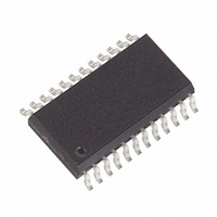
MAX132CWG+ Maxim Integrated Products, MAX132CWG+ Datasheet - Page 4

MAX132CWG+
Manufacturer Part Number
MAX132CWG+
Description
IC ADC 18BIT W/SRL INTRFC 24SOIC
Manufacturer
Maxim Integrated Products
Datasheet
1.MAX132CNG.pdf
(16 pages)
Specifications of MAX132CWG+
Number Of Bits
18
Sampling Rate (per Second)
100
Data Interface
MICROWIRE™, Serial, SPI™
Number Of Converters
1
Voltage Supply Source
Dual ±
Operating Temperature
0°C ~ 70°C
Mounting Type
Surface Mount
Package / Case
24-SOIC (0.300", 7.50mm Width)
Architecture
Dual Slope
Conversion Rate
0.1 KSPs
Input Type
Voltage
Interface Type
4-Wire (SPI, QSPI, MICROWIRE, TMS320)
Supply Voltage (max)
5 V
Maximum Power Dissipation
647 mW
Maximum Operating Temperature
+ 70 C
Mounting Style
SMD/SMT
Minimum Operating Temperature
0 C
Lead Free Status / RoHS Status
Lead free / RoHS Compliant
±18-Bit ADC with Serial Interface
4
__________________________________________Typical Operating Characteristics
______________________________________________________________Pin Description
PIN
-0.05
-0.10
-0.15
-0.20
-0.25
-0.30
100
140
120
0.05
-20
-40
_______________________________________________________________________________________
1
2
3
4
5
6
7
8
80
60
40
20
0
0
0
-4
IN HI = IN LO
INPUT VOLTAGE (V
-3
50
NAME
DOUT
OSC2
OSC1
SCLK
DIN
ERROR vs. COMMON-MODE
CS
COMMON-MODE VOLTAGE (V)
vs. CRYSTAL FREQUENCY
P0
P1
CRYSTAL FREQUENCY (kHz)
-2
100
SUPPLY CURRENT
-1
150
CHIP SELECT Input has 3 functions: 1) When low, selects IC for communication; 2) on rising edge, loads
input shift register data into one of the command registers; 3) on falling edge, loads data from one of the
output registers into the output shift register. When CS is high, DOUT is high impedance.
Serial Data In, D7 first bit in. Data is clocked into the register on the rising edge of SCLK.
Serial Data Out, D7 first bit out. Data is clocked out at the falling edge of SCLK. High impedance when CSis high.
Serial Clock Input. On SCLK’s rising edge, data is shifted into the internal shift register through DIN. On
SCLK’s falling edge, data is clocked out of DOUT.
Oscillator Output 2 is normally connected to a 32,768Hz crystal. Do not connect with external clock source.
Oscillator Input 1 is normally connected to a 32,768Hz crystal, or may be connected to an external clock.
User-programmable output bit 0—programmed through the serial port.
User-programmable output bit 1—programmed through the serial port.
0
200
IN
1
LO–AGND)
250
2
V+
V-
300
3
350
4
0.10
0.08
0.06
0.04
0.02
4.5
4.0
3.5
3.0
2.5
2.0
1.5
1.0
0.5
0
0
0
0
50Hz/60Hz READ-ZERO OFFSET
FULL-SCALE ROLLOVER ERROR
0.5
50Hz MODE
0.5
1.0
vs. VREF
vs. VREF
VREF (V)
VREF (V)
1.0
FUNCTION
1.5
60Hz MODE
1.5
2.0
2.0
2.5
1.6
1.4
1.2
1.0
0.8
0.6
0.4
0.2
20
15
10
0
5
0
-40
0
50Hz/60Hz READ-ZERO OFFSET
-20
NUMBER OF SAMPLES AVERAGED
10
OF SAMPLES AVERAGED
NOISE vs. NUMBER
vs. TEMPERATURE
0
TEMPERATURE (°C)
60Hz MODE, VREF = 545mV
50Hz MODE, VREF = 655mV
20
20
40
30
60
40
80
100
50


