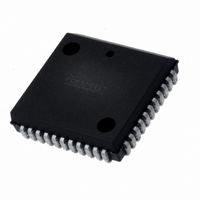
CS80C286-12 Intersil, CS80C286-12 Datasheet - Page 27

CS80C286-12
Manufacturer Part Number
CS80C286-12
Description
IC CPU 16BIT 5V 12.5MHZ 68-PLCC
Manufacturer
Intersil
Datasheet
1.CS80C286-12.pdf
(60 pages)
Specifications of CS80C286-12
Processor Type
80C286 16-Bit
Speed
12.5MHz
Voltage
5V
Mounting Type
Surface Mount
Package / Case
68-PLCC
Lead Free Status / RoHS Status
Contains lead / RoHS non-compliant
Features
-
Available stocks
Company
Part Number
Manufacturer
Quantity
Price
Company:
Part Number:
CS80C286-12
Manufacturer:
INTERSIL
Quantity:
5 510
Part Number:
CS80C286-12
Manufacturer:
HAR
Quantity:
20 000
synchronizes READY and RESET. The 82C288 converts
bus operation status encoded by the 80C286 into command
and bus control signals. The 82289 bus arbiter generates
Multibus™ bus arbitration signals. These components can
provide the critical timing required for most system bus inter-
faces including the Multibus.
Bus Hold Circuitry
To avoid high current conditions caused by floating inputs to
CMOS devices, and to eliminate the need for pull-up/down
resistors, “bus-hold” circuitry has been used on the 80C286
pins 4-6, 36-51 and 66-68 (See Figure 19A and 19B). The
circuit shown in Figure 19A will maintain the last valid logic
state if no driving source is present (i.e. an unconnected pin
or a driving source which goes to a high impedance state).
The circuit shown in Figure 19B will maintain a high imped-
ance logic one state if no driving source is present. To over-
drive the “bus-hold” circuits, an external driver must be
capable of sinking or sourcing approximately 400 microamps
at valid input voltage levels. Since this “bus-hold” circuitry is
active and not a “resistive” type element, the associated
power supply current is negligible, and power dissipation is
significantly reduced when compared to the use of passive
pull-up resistors.
Physical Memory and I/O Interface
A maximum of 16 megabytes of physical memory can be
addressed in protected mode. One megabyte can be
addressed in real address mode. Memory is accessible as
bytes or words. Words consist of any two consecutive bytes
addressed with the least significant byte stored in the lowest
DRIVER
DRIVER
OUTPUT
DRIVER
OUTPUT
INPUT
INPUT
DRIVER
FIGURE 19A. BUS HOLD CIRCUITRY, PINS 36-51, 66, 67
FIGURE 19B. BUS HOLD CIRCUITRY, PINS 4-6, 68
V
CC
P
PROTECTION
PROTECTION
CIRCUITRY
CIRCUITRY
INPUT
INPUT
BOND
BOND
PAD
PAD
EXTERNAL
PIN
EXTERNAL
PIN
80C286
27
address. Byte transfers occur on either half of the 16-bit local
data bus. Even bytes are accessed over D
are transferred over D
ferred over D
require two bus operations. The first transfers data on D
and the second transfers data on D
fers occur automatically, transparent to software.
Two bus signals, A
lower and upper halves of the data bus. Even address byte
transfers are indicated by A
address byte transfers are indicated by A
LOW. Both A
transfers.
The I/O address space contains 64K addresses in both
modes. The I/O space is accessible as either bytes or words,
as is memory. Byte wide peripheral devices may be attached
to either the upper or lower byte of the data bus. Byte-wide I/O
devices attached to the upper data byte (D
with odd I/O addresses. Devices on the lower data byte are
accessed with even I/O addresses. An interrupt controller
such as Intersil's 82C59A must be connected to the lower
data byte (D
Bus Operation
The 80C286 uses a double frequency system clock (CLK
input) to control bus timing. All signals on the local bus are
measured relative to the system CLK input. The CPU divides
the system clock by 2 to produce the internal processor
clock, which determines bus state. Each processor clock is
composed of two system clock cycles named phase 1 and
phase 2. The 82C284 clock generator output (PCLK) identi-
fies the next phase of the processor clock. (See Figure 20.)
Six types of bus operations are supported; memory read,
memory write, I/O read, I/O write, interrupt acknowledge,
and halt/shutdown. Data can be transferred at a maximum
rate of one word per two processor clock cycles.
The 80C286 bus has three basic states: idle (T
tus (T
has a fourth local bus state called hold (T
that the 80C286 has surrendered control of the local bus to
another bus master in response to a HOLD request.
Each bus state is one processor clock long. Figure 21 shows
the four 80C286 local bus states and allowed transitions.
FIGURE 20. SYSTEM AND PROCESSOR CLOCK RELATION-
PCLK
CLK
S
), and perform command (T
7-0
SHIPS
15-0
0
OF PROCESSOR
) for proper return of the interrupt vector.
CLOCK CYCLE
and BHE are LOW for even address word
ONE SYSTEM
CLK CYCLE
in one bus cycle, while odd addressed word
ONE PROCESSOR CLOCK CYCLE
PHASE 1
0
15-8
and BHE, control transfers over the
ONE BUS T STATE
. Even addressed words are trans-
0
LOW and BHE HIGH. Odd
C
OF PROCESSOR
7-0
CLOCK CYCLE
). The 80C286 CPU also
. Both byte data trans-
PHASE 2
7-0
15-8
0
H
HlGH and BHE
while odd bytes
). T
) are accessed
I
), send sta-
H
indicates
15-8
,


