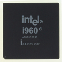
A80960CF33 Intel, A80960CF33 Datasheet - Page 27

A80960CF33
Manufacturer Part Number
A80960CF33
Description
IC MPU I960CF 33MHZ 168-PGA
Manufacturer
Intel
Datasheet
1.A80960CF33.pdf
(70 pages)
Specifications of A80960CF33
Processor Type
i960
Features
CF suffix, 32-Bit with DMA, 4K Cache
Speed
33MHz
Voltage
5V
Mounting Type
Surface Mount
Package / Case
168-PGA
Family Name
80960
Device Core Size
32b
Frequency (max)
33MHz
Instruction Set Architecture
RISC
Supply Voltage 1 (typ)
5V
Operating Supply Voltage (max)
5.5V
Operating Supply Voltage (min)
4.5V
Operating Temp Range
0C to 100C
Operating Temperature Classification
Commercial
Mounting
Through Hole
Pin Count
168
Package Type
CPGA
Lead Free Status / RoHS Status
Lead free / RoHS Compliant
Other names
803084
Available stocks
Company
Part Number
Manufacturer
Quantity
Price
4.3
4.4
Datasheet
Recommended Connections
Power and ground connections must be made to multiple V
80960CF-based circuit board should include power (V
distribution. Every V
connected to the ground plane. Pins identified as ‘NC’ must not be connected in the system.
Liberal decoupling capacitance should be placed near the 80960CF. The processor may cause
transient power surges when its numerous output buffers transition, particularly when connected to
large capacitive loads.
Low inductance capacitors and interconnects are recommended for best high frequency electrical
performance. Inductance may be reduced by shortening the board traces between the processor and
decoupling capacitors as much as possible. Capacitors specifically designed for PGA packages
may offer the lowest possible inductance.
For reliable operation, always connect unused inputs to an appropriate signal level. In particular,
any unused interrupt (XINT, NMI), DMA (DREQ), or BTERM input should be connected to V
through a pull-up resistor. Pull-up resistors should be in the in the range of 20 KW for each pin tied
high. When READY or HOLD are not used, the unused input should be connected to ground. N.C.
pins must always remain unconnected. For additional information refer to the i960
Microprocessor User’s Manual (order number 270710).
D.C. Specifications
Table 16
presents the D.C. specifications of the 80960CF.
CC
pin must be connected to the power plane, and every V
CC
) and ground (V
CC
and V
SS
(GND) pins. Every
SS
) planes for power
80960-40, -33, -25
SS
pin must be
®
CA/CF
CC
27


