MC68EC020FG25 Freescale Semiconductor, MC68EC020FG25 Datasheet - Page 269
MC68EC020FG25
Manufacturer Part Number
MC68EC020FG25
Description
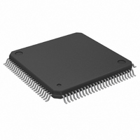
IC MPU 32 BIT 25MHZ 100-QFP
Manufacturer
Freescale Semiconductor
Datasheet
1.MC68EC020AA16.pdf
(306 pages)
Specifications of MC68EC020FG25
Processor Type
M680x0 32-Bit
Speed
25MHz
Voltage
5V
Mounting Type
Surface Mount
Package / Case
100-QFP
Lead Free Status / RoHS Status
Contains lead / RoHS non-compliant
Features
-
Available stocks
Company
Part Number
Manufacturer
Quantity
Price
Company:

Part Number:
MC68EC020FG25
Manufacturer:
FREESCALE
Quantity:
8 831
Company:
Part Number:
MC68EC020FG25
Manufacturer:
Freescale Semiconductor
Quantity:
10 000
Part Number:
MC68EC020FG25
Manufacturer:
MOTOROL
Quantity:
20 000


Another way to optimize the CPU-to-memory access times in a system is to use a clock
frequency less than the rated maximum of the specific MC68020/EC020 device. Table 9-5
provides calculated t
MC68020/EC020 and a 25 MHz MC68020/EC020 operating at various clock frequencies.
If the system uses other clock frequencies, the above equations can be used to calculate
the exact access times.
3 Clock Asynchronous
4 Clock Asynchronous
5 Clock Asynchronous
6 Clock Asynchronous
9.7 MODULE SUPPORT
The MC68020/EC020 includes support for modules with the CALLM and RTM
instructions. The CALLM instruction references a module descriptor. This descriptor
contains control information for entry into the called module. The CALLM instruction
creates a module stack frame and stores the current module state in that frame and loads
a new module state from the referenced descriptor. The RTM instruction recovers the
previous module state from the stack frame and returns to the calling module.
The module interface facilitates finer resolution of access control by external hardware.
Although the MC68020/EC020 does not interpret the access control information, it
communicates with external hardware when the access control is to be changed and
relies on the external hardware to verify that the changes are legal.
9.7.1 Module Descriptor
Figure 9-10 illustrates the format of the module descriptor. The first long word contains
control information used during execution of the CALLM instruction. The remaining
locations contain data that can be loaded into processor registers by the CALLM
instruction.
MOTOROLA
Clocks Per (N) and Type
Bus Cycle
Equation 9-7 t
Table 9-5. Calculated t
Less Than or Equal to the CPU Maximum Frequency Rating
AVDV
A V D V
States
Wait
0
1
2
3
(see Equation 9-7 of Table 9-4) results for a 16 MHz
12.5 MHz
16-MHz MC68020/EC020
Clock at
M68020 USER’S MANUAL
AVDV
181
261
341
421
Values for Operation at Frequencies
16.67 MHz
Clock at
121
181
241
301
16.67 MHz
Clock at
131
191
251
311
25-MHz MC68020/EC020
Clock at
20 MHz
101
151
201
251
Clock at
25 MHz
111
151
191
71
9- 15
Related parts for MC68EC020FG25
Image
Part Number
Description
Manufacturer
Datasheet
Request
R

Part Number:
Description:
Manufacturer:
Freescale Semiconductor, Inc
Datasheet:
Part Number:
Description:
Manufacturer:
Freescale Semiconductor, Inc
Datasheet:
Part Number:
Description:
Manufacturer:
Freescale Semiconductor, Inc
Datasheet:
Part Number:
Description:
Manufacturer:
Freescale Semiconductor, Inc
Datasheet:
Part Number:
Description:
Manufacturer:
Freescale Semiconductor, Inc
Datasheet:
Part Number:
Description:
Manufacturer:
Freescale Semiconductor, Inc
Datasheet:
Part Number:
Description:
Manufacturer:
Freescale Semiconductor, Inc
Datasheet:
Part Number:
Description:
Manufacturer:
Freescale Semiconductor, Inc
Datasheet:
Part Number:
Description:
Manufacturer:
Freescale Semiconductor, Inc
Datasheet:
Part Number:
Description:
Manufacturer:
Freescale Semiconductor, Inc
Datasheet:
Part Number:
Description:
Manufacturer:
Freescale Semiconductor, Inc
Datasheet:
Part Number:
Description:
Manufacturer:
Freescale Semiconductor, Inc
Datasheet:
Part Number:
Description:
Manufacturer:
Freescale Semiconductor, Inc
Datasheet:
Part Number:
Description:
Manufacturer:
Freescale Semiconductor, Inc
Datasheet:
Part Number:
Description:
Manufacturer:
Freescale Semiconductor, Inc
Datasheet: