MC68EC020FG25 Freescale Semiconductor, MC68EC020FG25 Datasheet - Page 46
MC68EC020FG25
Manufacturer Part Number
MC68EC020FG25
Description
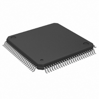
IC MPU 32 BIT 25MHZ 100-QFP
Manufacturer
Freescale Semiconductor
Datasheet
1.MC68EC020AA16.pdf
(306 pages)
Specifications of MC68EC020FG25
Processor Type
M680x0 32-Bit
Speed
25MHz
Voltage
5V
Mounting Type
Surface Mount
Package / Case
100-QFP
Lead Free Status / RoHS Status
Contains lead / RoHS non-compliant
Features
-
Available stocks
Company
Part Number
Manufacturer
Quantity
Price
Company:

Part Number:
MC68EC020FG25
Manufacturer:
FREESCALE
Quantity:
8 831
Company:
Part Number:
MC68EC020FG25
Manufacturer:
Freescale Semiconductor
Quantity:
10 000
Part Number:
MC68EC020FG25
Manufacturer:
MOTOROL
Quantity:
20 000


4.2 CACHE RESET
During processor reset, the cache is cleared by resetting all of the valid bits. The E and F
bits in the CACR are also cleared.
4.3 CACHE CONTROL
Only the MC68020/EC020 cache control circuitry can directly access the cache array, but
a supervisor program can set bits in the CACR to exercise control over cache operations.
The supervisor level also has access to the CAAR, which contains the address for a
cache entry to be cleared.
System hardware can assert the CDIS signal to disable the cache. The assertion of CDIS
disables the cache, regardless of the state of the E-bit in the CACR. CDIS is primarily
intended for use by in-circuit emulators.
4.3.1 Cache Control Register (CACR)
The CACR, shown in Figure 4-2, is a 32-bit register than can be written or read by the
MOVEC instruction or indirectly modified by a reset. Four of the bits (3–0) control the
instruction cache. Bits 31–4 are reserved for Motorola definition. They are read as zeros
and are ignored when written. For future compatibility, writes should not set these bits.
C—Clear Cache
CE—Clear Entry In Cache
MOTOROLA
31
The C-bit is set to clear all entries in the instruction cache. Operating systems and other
software set this bit to clear instructions from the cache prior to a context switch. The
processor clears all valid bits in the instruction cache when a MOVEC instruction sets
the C-bit. The C-bit is always read as a zero.
The CE bit is set to clear an entry in the instruction cache. The index field of the CAAR
(see Figure 4-3), corresponding to the index and long-word select portion of an address,
specifies the entry to be cleared. The processor clears only the specified long word by
clearing the valid bit for the entry when a MOVEC instruction sets the CE bit, regardless
of the states of the E and F bits. The CE bit is always read as a zero.
Figure 4-2. Cache Control Register
0
M68020 USER’S MANUAL
8
7
0
6
0
5
0
4
0
C
3
CE
2
F
1
0
E
4- 3
Related parts for MC68EC020FG25
Image
Part Number
Description
Manufacturer
Datasheet
Request
R

Part Number:
Description:
Manufacturer:
Freescale Semiconductor, Inc
Datasheet:
Part Number:
Description:
Manufacturer:
Freescale Semiconductor, Inc
Datasheet:
Part Number:
Description:
Manufacturer:
Freescale Semiconductor, Inc
Datasheet:
Part Number:
Description:
Manufacturer:
Freescale Semiconductor, Inc
Datasheet:
Part Number:
Description:
Manufacturer:
Freescale Semiconductor, Inc
Datasheet:
Part Number:
Description:
Manufacturer:
Freescale Semiconductor, Inc
Datasheet:
Part Number:
Description:
Manufacturer:
Freescale Semiconductor, Inc
Datasheet:
Part Number:
Description:
Manufacturer:
Freescale Semiconductor, Inc
Datasheet:
Part Number:
Description:
Manufacturer:
Freescale Semiconductor, Inc
Datasheet:
Part Number:
Description:
Manufacturer:
Freescale Semiconductor, Inc
Datasheet:
Part Number:
Description:
Manufacturer:
Freescale Semiconductor, Inc
Datasheet:
Part Number:
Description:
Manufacturer:
Freescale Semiconductor, Inc
Datasheet:
Part Number:
Description:
Manufacturer:
Freescale Semiconductor, Inc
Datasheet:
Part Number:
Description:
Manufacturer:
Freescale Semiconductor, Inc
Datasheet:
Part Number:
Description:
Manufacturer:
Freescale Semiconductor, Inc
Datasheet: