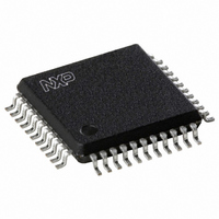
UDA1384H/N1,518 NXP Semiconductors, UDA1384H/N1,518 Datasheet - Page 23

UDA1384H/N1,518
Manufacturer Part Number
UDA1384H/N1,518
Description
IC AUDIO CODER/DECODER 44QFP
Manufacturer
NXP Semiconductors
Type
Audio Codecr
Datasheet
1.UDA1384HN1557.pdf
(55 pages)
Specifications of UDA1384H/N1,518
Data Interface
I²C, Serial
Resolution (bits)
24 b
Number Of Adcs / Dacs
5 / 6
Sigma Delta
No
S/n Ratio, Adcs / Dacs (db) Typ
98 / 110 (Differential), 98 / 110 (Single-Ended)
Voltage - Supply, Analog
2.7 V ~ 3.6 V
Voltage - Supply, Digital
2.7 V ~ 3.6 V
Operating Temperature
-20°C ~ 85°C
Mounting Type
Surface Mount
Package / Case
44-MQFP, 44-PQFP
Lead Free Status / RoHS Status
Lead free / RoHS Compliant
Other names
935274756518
UDA1384H-T
UDA1384H-T
UDA1384H-T
UDA1384H-T
Available stocks
Company
Part Number
Manufacturer
Quantity
Price
Company:
Part Number:
UDA1384H/N1,518
Manufacturer:
NXP Semiconductors
Quantity:
10 000
Philips Semiconductors
Table 19:
[1]
11. Register mapping
9397 750 14366
Product data sheet
S 0011 000 0
Device
address
A = acknowledge from UDA1384
Auto increment of register address.
Master transmitter reads from the UDA1384 registers in the I
R/W
11.1 Address mapping
A ADDR
Register
address
In this chapter the register addressing and mapping of the microcontroller interface of the
UDA1384 is given.
In
In
in
Table 20:
Address
System settings
00h
01h
02h
Status (read out registers)
0Fh
Interpolator settings
10h
11h
12h
13h
14h
15h
7. Then the microcontroller generates the device address ‘0011 000’ again, but this time
8. The UDA1384 sends 2 bytes data with the Most Significant (MS) byte first and then
9. If repeated groups of 2 bytes are transmitted, then the register address is auto
10.The microcontroller stops this cycle by generating a Negative Acknowledge (NA).
11.Finally, the UDA1384 frees the I
Section 11.3
Table 20
Table 21
followed by a logic 1 (read) of the R/W bit. An acknowledge is followed from the
UDA1384.
the Least Significant (LS) byte. After each byte an acknowledge is followed from the
microcontroller (master).
incremented. After each byte an acknowledge is followed from the microcontroller.
condition (P).
A Sr 0011 000 1 A MS1 A LS1 A MS2 A LS2 A MSn A LSn NA
Overview of register mapping
an overview of the register mapping is given.
the actual register mapping is given and the register definitions are explained
Function
system
audio ADC and DAC subsystem
voice ADC system
status outputs
DAC channel and feature selection
DAC feature control
DAC channel 1
DAC channel 2
DAC channel 3
DAC channel 4
Device
address
to
Section
Rev. 02 — 17 January 2005
R/W Data 1
11.14.
A = acknowledge from master
2
C-bus and the microcontroller can generate a stop
2
Data 2
C-bus mode
Multichannel audio coder-decoder
[1]
© Koninklijke Philips Electronics N.V. 2005. All rights reserved.
Data n
UDA1384
[1]
23 of 55
P


