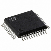
UDA1384H/N1,518 NXP Semiconductors, UDA1384H/N1,518 Datasheet - Page 27

UDA1384H/N1,518
Manufacturer Part Number
UDA1384H/N1,518
Description
IC AUDIO CODER/DECODER 44QFP
Manufacturer
NXP Semiconductors
Type
Audio Codecr
Datasheet
1.UDA1384HN1557.pdf
(55 pages)
Specifications of UDA1384H/N1,518
Data Interface
I²C, Serial
Resolution (bits)
24 b
Number Of Adcs / Dacs
5 / 6
Sigma Delta
No
S/n Ratio, Adcs / Dacs (db) Typ
98 / 110 (Differential), 98 / 110 (Single-Ended)
Voltage - Supply, Analog
2.7 V ~ 3.6 V
Voltage - Supply, Digital
2.7 V ~ 3.6 V
Operating Temperature
-20°C ~ 85°C
Mounting Type
Surface Mount
Package / Case
44-MQFP, 44-PQFP
Lead Free Status / RoHS Status
Lead free / RoHS Compliant
Other names
935274756518
UDA1384H-T
UDA1384H-T
UDA1384H-T
UDA1384H-T
Available stocks
Company
Part Number
Manufacturer
Quantity
Price
Company:
Part Number:
UDA1384H/N1,518
Manufacturer:
NXP Semiconductors
Quantity:
10 000
Philips Semiconductors
9397 750 14366
Product data sheet
11.3 System settings
Table 22:
Table 23:
Bit
15
14 to 13
12
11
10
9 to 8
7 to 6
5 to 4
3
2
Bit
Symbol
Reset
Access
Bit
Symbol
Reset
Access
Symbol
RST
VFS[1:0]
VCE
VAP
DSD
SC[1:0]
OP[1:0]
FS[1:0]
ACE
ADP
System register (address 00h) bit allocation
Description of system register bits
RST
OP1
15
7
0
-
Description
Reset. Bit RST initializes the L3-bus registers with the default settings.
Voice ADC sampling frequency. A 2-bit value to select the voice ADC
sampling frequency. Default 00. See
Voice ADC clock enable.
Voice ADC power control. Bit VAP is to reduce the power consumption of
the voice ADC.
DSD mode selection. Bit DSD selects the DSD mode.
System clock frequency. A 2-bit value to select the used external clock
frequency. 128f
bit DVD = 1. Default 00. See
Operating mode selection. A 2-bit value to select the operation mode of
the audio ADC and DAC. Default 00. See
Sampling frequency. A 2-bit value to select the sampling frequency of the
audio ADC and DAC in the WS mode. Default 01. See
ADC clock enable. Bit ACE enables the audio ADC clock
ADC power control. Bit ADP is to reduce the power consumption of the
audio ADC.
Rev. 02 — 17 January 2005
VFS1
OP0
1 = Reset to default settings
0 = No reset
1 = clock enabled (default)
0 = clock disabled
1 = state is power-on
0 = state is power-off (default)
1 = DSD mode
0 = normal mode (default)
1 = clock enabled (default)
0 = clock disabled
1 = state is power-on
0 = state is power-off (default)
14
0
6
0
VFS0
FS1
13
0
5
0
s
system clock for the DAC can be used by setting
VCE
FS0
read and write
read and write
12
1
4
1
Table
25.
ACE
Multichannel audio coder-decoder
VAP
11
Table
0
3
1
© Koninklijke Philips Electronics N.V. 2005. All rights reserved.
Table
24.
DSD
ADP
10
26.
0
2
0
UDA1384
Table
DCE
SC1
9
0
1
1
27.
SC0
DAP
27 of 55
8
0
0
0


