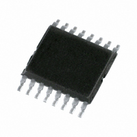
SC18IS602BIPW,112 NXP Semiconductors, SC18IS602BIPW,112 Datasheet - Page 13

SC18IS602BIPW,112
Manufacturer Part Number
SC18IS602BIPW,112
Description
IC BRIDGE SPI/I2C 16-TSSOP
Manufacturer
NXP Semiconductors
Specifications of SC18IS602BIPW,112
Controller Type
I²C Bus Controller
Interface
I²C
Voltage - Supply
2.4 V ~ 3.6 V
Current - Supply
11mA
Operating Temperature
-40°C ~ 85°C
Mounting Type
Surface Mount
Package / Case
16-TSSOP
Operating Temperature Classification
Military
Operating Temperature (max)
125C
Package Type
TSSOP
Rad Hardened
No
Maximum Operating Frequency
4.5 MHz
Maximum Operating Temperature
+ 125 C
Minimum Operating Temperature
- 55 C
Mounting Style
SMD/SMT
Supply Voltage (max)
3.6 V
Supply Voltage (min)
2.4 V
For Use With
568-4705 - DEMO BOARD I2C TO SPI SC18IS602
Lead Free Status / RoHS Status
Lead free / RoHS Compliant
Other names
568-4785-5
935286182112
SC18IS602BIPW
SC18IS602BIPW,112
SC18IS602BIPW
935286182112
SC18IS602BIPW
SC18IS602BIPW,112
SC18IS602BIPW
Available stocks
Company
Part Number
Manufacturer
Quantity
Price
Company:
Part Number:
SC18IS602BIPW,112
Manufacturer:
NXP
Quantity:
463
NXP Semiconductors
8. I
SC18IS602B
Product data sheet
2
C-bus to SPI communications example
7.2 SPI interface
The SPI interface can support Mode 0 through Mode 3 of the SPI specification and can
operate up to 1.8 Mbit/s. The SPI interface uses at least four pins: SPICLK, MOSI, MISO,
and Slave Select (SSn).
SSn are the slave select pins. In a typical configuration, an SPI master selects one SPI
device as the current slave.
There are actually four SSn pins (SS0, SS1, SS2 and SS3) to allow the SC18IS602B to
communicate with multiple SPI devices.
The SC18IS602B generates the SPICLK (SPI clock) signal in order to send and receive
data. The SCLK, MOSI, and MISO are typically tied together between two or more SPI
devices. Data flows from the SC18IS602B (master) to slave on the MOSI pin (Pin 6) and
the data flows from slave to SC18IS602B (master) on the MISO pin (Pin 5).
The following example describes a typical sequence of events required to read the
contents of an SPI-based EEPROM. This example assumes that the SC18IS602B is
configured to respond to address 50h. A START condition is shown as ‘ST’, while a STOP
condition is ‘SP’. The data is presented in hexadecimal format.
1. The first message is used to configure the SPI port for mode and frequency.
2. An SPI EEPROM first requires that a Write Enable command be sent before data can
3. Clear the interrupt. This is not required if using a polling method rather than interrupts.
4. Write the 8 data bytes. The first byte (Function ID) tells the SC18IS602B which Slave
5. When an interrupt occurs, do a Clear Interrupt or wait until the SC18IS602B responds
be written.
Select output to use. This example uses SS2 (shown as 04h). The first byte sent to
the EEPROM is normally 02h for the EEPROM write command. The next one or two
bytes represent the subaddress in the EEPROM. In this example, a two-byte
subaddress is used. Bytes 00 and 30 would cause the EEPROM to write to
subaddress 0030h. The next eight bytes are the eight data bytes that will be written to
subaddresses 0030h through 0037h.
to its I
ST,50,F0,02,SP
ST,50,04,06,SP
ST,50,F1,SP
ST,50,04,02,00,30,01,02,03,04,05,06,07,08,SP
ST,50,F1,SP
2
C-bus address.
All information provided in this document is subject to legal disclaimers.
Rev. 5 — 3 August 2010
SPI frequency 115 kHz using Mode 0
EEPROM write enable using SS2, assuming the Write Enable is
06h
Clear interrupt
Clear interrupt
Write 8 bytes using SS2
SC18IS602B
I
2
C-bus to SPI bridge
© NXP B.V. 2010. All rights reserved.
13 of 25


