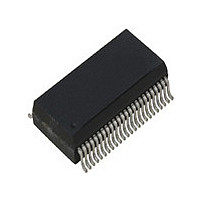
ICS1893BF IDT, Integrated Device Technology Inc, ICS1893BF Datasheet - Page 19

ICS1893BF
Manufacturer Part Number
ICS1893BF
Description
PHYCEIVER LOW PWR 3.3V 48-SSOP
Manufacturer
IDT, Integrated Device Technology Inc
Series
PHYceiver™r
Type
PHY Transceiverr
Specifications of ICS1893BF
Protocol
MII
Voltage - Supply
3.14 V ~ 3.47 V
Mounting Type
Surface Mount
Package / Case
48-SSOP
Lead Free Status / RoHS Status
Contains lead / RoHS non-compliant
Number Of Drivers/receivers
-
Lead Free Status / Rohs Status
Not Compliant
Other names
1893BF
Available stocks
Company
Part Number
Manufacturer
Quantity
Price
Part Number:
ICS1893BF
Manufacturer:
ICS
Quantity:
20 000
Company:
Part Number:
ICS1893BFI
Manufacturer:
OKI
Quantity:
1 934
Part Number:
ICS1893BFILF
Manufacturer:
ICS
Quantity:
20 000
Company:
Part Number:
ICS1893BFLF
Manufacturer:
ICS
Quantity:
409
Part Number:
ICS1893BFLF
Manufacturer:
ICS
Quantity:
20 000
Part Number:
ICS1893BFLFT
Manufacturer:
IDT
Quantity:
20 000
4.1.2.3 Software Reset
4.2 Power-Down Operations
ICS1893BF, Rev. F, 5/13/10
Entering Software Reset
Initiation of a software reset occurs when a management entity writes a logic one to Control Register bit
0.15. When this write occurs, the ICS1893BF enters the reset state for two REF_IN clock cycles.
Note:
Exiting Software Reset
At the completion of a reset (either hardware, power-on, or software), the ICS1893BF sets all registers to
their default values. This action automatically clears (that is, sets equal to logic zero) Control Register bit
0.15, the software reset bit. Therefore, for a software reset (only), bit 0.15 is a self-clearing bit that indicates
the completion of the reset process.
Note:
1. The RESETn pin is active low but Control Register bit 0.15 is active high.
2. Exiting a software reset is nearly identical to exiting a hardware reset or a power-on reset, except that
3. The Control Register bit 0.15 does not represent the status of a hardware reset. It is a self-clearing bit
The ICS1893BF enters the power-down state whenever either (1) the RESETn pin is low or (2) Control
Register bit 0.11 (the Power-Down bit) is logic one. In the power-down state, the ICS1893BF disables all
internal functions and drives all MAC Interface output pins to logic zero except for those that support the MII
Serial Management Port. In addition, the ICS1893BF tri-states its Twisted-Pair Transmit pins (TP_TXP and
TP_TXN) to achieve an additional reduction in power.
There is one significant difference between entering the power-down state by setting Control Register bit
0.11 as opposed to entering the power-down state during a reset. When the ICS1893BF enters the
power-down state:
•
•
For more information on power-down operations, see the following:
•
•
By setting Control Register bit 0.11, the ICS1893BF maintains the value of all Management Register bits
except for the latching low (LL), latching high (LH), and latching maximum (LMX) status bits. Instead,
these LL, LH, and LMX Management Register bits are re-initialized to their default values.
During a reset, the ICS1893BF sets all of its Management Register bits to their default values. It does not
maintain the state of any Management Register bit.
Section 7.14, “Register 19: Extended Control Register 2”
Section 9.4, “DC Operating
consumption while in the power-down state
upon exiting a software-initiated reset, the ICS1893BF does not re-latch its Serial Management Port
Address into the Extended Control Register. [For information on the Serial Management Port Address,
see
that is used to initiate a software reset. During a hardware or power-on reset, Control Register bit 0.15
does not get set to logic one. As a result, this bit 0.15 cannot be used to indicate the completion of the
reset process for hardware or power-on resets.
ICS1893BF Data Sheet Rev. F - Release
Entering a software reset is nearly identical to entering a hardware reset or a power-on reset,
except that during a software-initiated reset, the ICS1893BF does not enter the power-down state.
Section 7.11.3, “PHY Address (bits
Characteristics”, which has tables that specify the ICS1893BF power
Copyright © 2009, IDT, Inc.
16.10:6)”.]
All rights reserved.
19
Chapter 4 Operating Modes Overview
May, 2010


