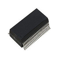
ICS1893BF IDT, Integrated Device Technology Inc, ICS1893BF Datasheet - Page 96

ICS1893BF
Manufacturer Part Number
ICS1893BF
Description
PHYCEIVER LOW PWR 3.3V 48-SSOP
Manufacturer
IDT, Integrated Device Technology Inc
Series
PHYceiver™r
Type
PHY Transceiverr
Specifications of ICS1893BF
Protocol
MII
Voltage - Supply
3.14 V ~ 3.47 V
Mounting Type
Surface Mount
Package / Case
48-SSOP
Lead Free Status / RoHS Status
Contains lead / RoHS non-compliant
Number Of Drivers/receivers
-
Lead Free Status / Rohs Status
Not Compliant
Other names
1893BF
Available stocks
Company
Part Number
Manufacturer
Quantity
Price
Part Number:
ICS1893BF
Manufacturer:
ICS
Quantity:
20 000
Company:
Part Number:
ICS1893BFI
Manufacturer:
OKI
Quantity:
1 934
Part Number:
ICS1893BFILF
Manufacturer:
ICS
Quantity:
20 000
Company:
Part Number:
ICS1893BFLF
Manufacturer:
ICS
Quantity:
409
Part Number:
ICS1893BFLF
Manufacturer:
ICS
Quantity:
20 000
Part Number:
ICS1893BFLFT
Manufacturer:
IDT
Quantity:
20 000
8.2.3 Configuration Pins
ICS1893BF, Rev. F, 5/13/10
Table 8-6
Table 8-6. Configuration Pins
10/100SEL
10TCSR
100TCSR
REF_IN
REF_OUT
RESETn
Name
Pin
ICS1893BF Data Sheet - Release
lists the configuration pins.
Number
Pin
19
20
47
46
23
9
Output
Output
Output
Output
Type
Input
Input
Pin
10Base-T / 100Base-TX Select.
10M Transmit Current Set Resistor.
100M Transmit Current Set Resistor.
(Frequency) Reference Input.
This pin is connected to a 25-MHz oscillator. For a tolerance, see
Section 9.5.1, “Timing for Clock Reference In (REF_IN)
(Frequency) Reference Output.
This pin is used with a crystal.
(System) Reset (Active Low).
•
•
•
•
•
•
•
Copyright © 2009, IDT, Inc.
This pin acts as an output that indicates the current status of this
pin. In this case, when the signal on this pin is logic:
– Low, this pin indicates 10Base-T operations are selected.
– High, this pin indicates 100Base-TX operations are selected.
A resistor, connected between this pin and ground, is required to
establish the value of the transmit current used in 10Base-T mode.
The value and tolerance of this resistor is specified in
“Recommended Component
A resistor, connected between this pin and ground, is required to
establish the value of the transmit current used in 100Base-TX
mode.
The value and tolerance of this resistor is specified in
“Recommended Component
When the signal on this active-low pin is logic:
– Low, the ICS1893BF is in hardware reset.
– High, the ICS1893BF is operational.
For more information on hardware resets, see the following:
–
–
Section 4.1.2.1, “Hardware Reset”
Section 9.5.16, “Reset: Hardware Reset and Power-Down”
All rights reserved.
96
Chapter 8 Pin Diagram, Listings, and Descriptions
Pin Description
Values”.
Values”.
Pin”.
Section 9.3,
Section 9.3,
May, 2010


