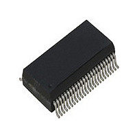
ICS1893BF IDT, Integrated Device Technology Inc, ICS1893BF Datasheet - Page 82

ICS1893BF
Manufacturer Part Number
ICS1893BF
Description
PHYCEIVER LOW PWR 3.3V 48-SSOP
Manufacturer
IDT, Integrated Device Technology Inc
Series
PHYceiver™r
Type
PHY Transceiverr
Specifications of ICS1893BF
Protocol
MII
Voltage - Supply
3.14 V ~ 3.47 V
Mounting Type
Surface Mount
Package / Case
48-SSOP
Lead Free Status / RoHS Status
Contains lead / RoHS non-compliant
Number Of Drivers/receivers
-
Lead Free Status / Rohs Status
Not Compliant
Other names
1893BF
Available stocks
Company
Part Number
Manufacturer
Quantity
Price
Part Number:
ICS1893BF
Manufacturer:
ICS
Quantity:
20 000
Company:
Part Number:
ICS1893BFI
Manufacturer:
OKI
Quantity:
1 934
Part Number:
ICS1893BFILF
Manufacturer:
ICS
Quantity:
20 000
Company:
Part Number:
ICS1893BFLF
Manufacturer:
ICS
Quantity:
409
Part Number:
ICS1893BFLF
Manufacturer:
ICS
Quantity:
20 000
Part Number:
ICS1893BFLFT
Manufacturer:
IDT
Quantity:
20 000
7.12.6 False Carrier (bit 17.8)
7.12.7 Invalid Symbol (bit 17.7)
7.12.8 Halt Symbol (bit 17.6)
ICS1893BF, Rev. F, 5/13/10
The False Carrier bit indicates to an STA the detection of a False Carrier by the ICS1893BF in 100Base
mode.
A False Carrier occurs when the ICS1893BF begins evaluating potential data on the incoming 100Base
data stream, only to learn that it was not a valid /J/K/. If this bit is set to a logic:
•
•
This bit is a latching high bit. (For more information on latching high and latching low bits, see
7.1.4.1, “Latching High Bits”
Note:
The Invalid Symbol bit indicates to an STA the detection of an Invalid Symbol in a 100Base data stream by
the ICS1893BF.
When the ICS1893BF is receiving a packet, it examines each received Symbol to ensure the data is error
free. If an error occurs, the port indicates this condition to the MAC by asserting the RXER signal. In
addition, the ICS1893BF sets its Invalid Symbol bit to logic one. Therefore, if this bit is set to a logic:
•
•
This bit is a latching high bit. (For more information on latching high and latching low bits, see
7.1.4.1, “Latching High Bits”
Note:
The Halt Symbol bit indicates to an STA the detection of a Halt Symbol in a 100Base data stream by the
ICS1893BF.
During reception of a valid packet, the ICS1893BF examines each symbol to ensure that the data being
passed to the MAC Interface is error free. In addition, it looks for special symbols such as the Halt Symbol.
If a Halt Symbol is encountered, the ICS1893BF indicates this condition to the MAC.
If this bit is set to a logic:
•
•
This bit is a latching high bit. (For more information on latching high and latching low bits, see
7.1.4.1, “Latching High Bits”
Note:
Zero, it indicates a False Carrier has not been detected since either the last read or reset of this register.
One, it indicates a False Carrier was detected since either the last read or reset of this register.
Zero, it indicates an Invalid Symbol has not been detected since either the last read or reset of this
register.
One, it indicates an Invalid Symbol was detected since either the last read or reset of this register.
Zero, it indicates a Halt Symbol has not been detected since either the last read or reset of this register.
One, it indicates a Halt Symbol was detected in the packet since either the last read or reset of this
register.
ICS1893BF Data Sheet - Release
This bit has no definition in 10Base-T mode.
This bit has no definition in 10Base-T mode.
This bit has no definition in 10Base-T mode.
and
and
and
Section 7.1.4.2, “Latching Low
Section 7.1.4.2, “Latching Low
Section 7.1.4.2, “Latching Low
Copyright © 2009, IDT, Inc.
All rights reserved.
82
Bits”.)
Bits”.)
Bits”.)
Chapter 7 Management Register Set
Section
Section
Section
May, 2010


