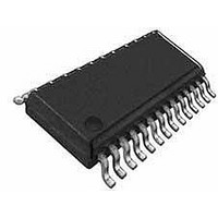
ST62T65CN6 STMicroelectronics, ST62T65CN6 Datasheet - Page 41

ST62T65CN6
Manufacturer Part Number
ST62T65CN6
Description
Microcontrollers (MCU) OTP EPROM 4K SPI
Manufacturer
STMicroelectronics
Datasheet
1.ST62T55CM6.pdf
(86 pages)
Specifications of ST62T65CN6
Processor Series
ST62T6x
Core
ST6
Data Bus Width
8 bit
Program Memory Type
EPROM
Program Memory Size
3884 B
Data Ram Size
128 B
Interface Type
SCI
Maximum Clock Frequency
8 MHz
Number Of Programmable I/os
21
Number Of Timers
1
Operating Supply Voltage
3 V to 6 V
Maximum Operating Temperature
+ 125 C
Mounting Style
SMD/SMT
Package / Case
SSOP-28
Minimum Operating Temperature
- 40 C
On-chip Adc
8 bit
Lead Free Status / Rohs Status
Details
Available stocks
Company
Part Number
Manufacturer
Quantity
Price
Company:
Part Number:
ST62T65CN6
Manufacturer:
SEK
Quantity:
1 000
Part Number:
ST62T65CN6
Manufacturer:
ST
Quantity:
20 000
I/O PORTS (Cont’d)
4.1.3 Timer 1 Alternate function Option
When bit TOUT of register TSCR1 is low, pin PC1/
Timer 1 is configured through the port registers as
any standard pin of Port B. It is in addition connect-
ed to the Timer 1 input for Gated and Event coun-
ter modes. When bit TOUT of register TSCR1 is
high, pin PC1/Timer 1 is forced as Timer 1 output,
independently of the port registers configuration.
4.1.4 AR Timer Alternate function Option
When bit PWMOE of register ARMC is low, pin AR-
TIMout/PB7 is configured as any standard pin of
port B through the port registers. When PWMOE is
high, ARTIMout/PB7 is the PWM output, independ-
ently of the port registers configuration.
ARTIMin/PB6 is connected to the AR Timer input.
It is configured through the port registers as any
standard pin of port B. To use ARTIMin/PB6 as AR
Timer input, it must be configured as input through
DDRB.
4.1.5 SPI Alternate function Option
PC2/PC4 are used as standard I/O as long as bit
SPCLK of the SPI Mode Register is kept low.
When PC2/Sin is configured as input, it is automat-
ically connected to the SPI shift register input, in-
dependent of the state at SPCLK.
PC3/SOUT is configured as SPI push-pull output
by setting bit 0 of the Miscellaneous register (ad-
dress DDh), regardless of the state of Port C reg-
isters. PC4/SCK is configured as push-pull output
clock (master mode) by programming it as push-
pull output through DDRC register and by setting
bit SPCLK of the SPI Mode Register.
PC4/SCK is configured as input clock (slave mode)
by programming it as input through DDRC register
and by clearing bit SPCLK of the SPI Mode Regis-
ter. With this configuration, PC4 can simultaneous-
ly be used as an input.
ST62T55C ST62T65C/E65C
41/86


