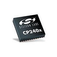
CP2401-GQ Silicon Laboratories Inc, CP2401-GQ Datasheet - Page 106

CP2401-GQ
Manufacturer Part Number
CP2401-GQ
Description
IC LCD DRIVER 48TQFP
Manufacturer
Silicon Laboratories Inc
Specifications of CP2401-GQ
Package / Case
48-TQFP, 48-VQFP
Display Type
LCD
Configuration
128 Segment
Interface
I²C, SMBus
Current - Supply
620µA
Voltage - Supply
1.8 V ~ 3.6 V
Operating Temperature
-40°C ~ 85°C
Mounting Type
Surface Mount
Data Ram Size
256 B
Interface Type
I2C, SMBus
Maximum Clock Frequency
25 MHz
Number Of Timers
2
Operating Supply Voltage
1.8 V to 3.6 V
Maximum Operating Temperature
+ 85 C
Mounting Style
SMD/SMT
Minimum Operating Temperature
- 40 C
Lead Free Status / RoHS Status
Lead free / RoHS Compliant
Digits Or Characters
-
Lead Free Status / Rohs Status
Lead free / RoHS Compliant
Other names
336-1860
Available stocks
Company
Part Number
Manufacturer
Quantity
Price
Company:
Part Number:
CP2401-GQ
Manufacturer:
Silicon Laboratories Inc
Quantity:
10 000
Part Number:
CP2401-GQ
Manufacturer:
SILICON LABS/芯科
Quantity:
20 000
Company:
Part Number:
CP2401-GQR
Manufacturer:
Silicon Laboratories Inc
Quantity:
10 000
CP2400/1/2/3
15.3.3. SCL Low Timeout
If the SCL line is held low by a slave device on the bus, no further communication is possible. Furthermore, the
master cannot force the SCL line high to correct the error condition. To solve this problem, the SMBus protocol
specifies that devices participating in a transfer must detect any clock cycle held low longer than 25 ms as a
“timeout” condition. Devices that have detected the timeout condition must reset the communication no later than
10 ms after detecting the timeout condition.
When SMBus is used for communication with the host microcontroller, Timer 0 is used to detect SCL low timeouts.
Timer 0 is forced to reload when SCL is high, and allowed to count when SCL is low. With Timer 0 enabled and
configured to overflow after 25 ms, the Timer 0 interrupt service routine can be used to alert the host
microcontroller of an SCL Low Timeout. After an SCL Low Timeout, the SMBus slave will reset its internal state
machine and will be ready to respond to new transfers. On reset or wake-up from ULP mode, Timer 0 is enabled
and configured for SCL Low Timeout detection. The SCL Low Timeout may be disabled by clearing the SMBTOE
bit in the SMB0CF register. This allows full software control of Timer 0.
15.3.4. SCL High (SMBus Free) Timeout
The SMBus specification stipulates that if the SCL and SDA lines remain high for more that 50 µs, the bus is
designated as free. When the SMBFTE bit in SMB0CF is set, the bus will be considered free if SCL and SDA
remain high for more than 1250 system clock periods. After an SCL High Timeout, the SMBus slave will reset its
internal state machine and will be ready to respond to new transfers.
15.3.5. Slave Address Selection
CP2400/1/2/3 devices can have one of 2 possible 7-bit, left-justified slave addresses: 0x74 and 0x76. The least
significant bit of the slave address is set by the SMBA0 pin. The remaining bits in the slave address are fixed. The
bit following the least significant address bit is used to indicate whether the current transfer is a read or a write.
106
Rev. 1.0


