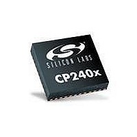
CP2401-GQ Silicon Laboratories Inc, CP2401-GQ Datasheet - Page 74

CP2401-GQ
Manufacturer Part Number
CP2401-GQ
Description
IC LCD DRIVER 48TQFP
Manufacturer
Silicon Laboratories Inc
Specifications of CP2401-GQ
Package / Case
48-TQFP, 48-VQFP
Display Type
LCD
Configuration
128 Segment
Interface
I²C, SMBus
Current - Supply
620µA
Voltage - Supply
1.8 V ~ 3.6 V
Operating Temperature
-40°C ~ 85°C
Mounting Type
Surface Mount
Data Ram Size
256 B
Interface Type
I2C, SMBus
Maximum Clock Frequency
25 MHz
Number Of Timers
2
Operating Supply Voltage
1.8 V to 3.6 V
Maximum Operating Temperature
+ 85 C
Mounting Style
SMD/SMT
Minimum Operating Temperature
- 40 C
Lead Free Status / RoHS Status
Lead free / RoHS Compliant
Digits Or Characters
-
Lead Free Status / Rohs Status
Lead free / RoHS Compliant
Other names
336-1860
Available stocks
Company
Part Number
Manufacturer
Quantity
Price
Company:
Part Number:
CP2401-GQ
Manufacturer:
Silicon Laboratories Inc
Quantity:
10 000
Part Number:
CP2401-GQ
Manufacturer:
SILICON LABS/芯科
Quantity:
20 000
Company:
Part Number:
CP2401-GQR
Manufacturer:
Silicon Laboratories Inc
Quantity:
10 000
CP2400/1/2/3
11.2. SmaRTClock Clocking Sources
The SmaRTClock peripheral is clocked from its own timebase, independent of the system clock. The SmaRTClock
timebase is derived from the SmaRTClock oscillator circuit, which has two modes of operation: crystal mode, and
self-oscillate mode. The oscillation frequency is 32.768 kHz in crystal mode and can be programmed in the range
of sub 20 kHz to above 40 kHz in self-oscillate mode. In crystal mode, XTAL1 and XTAL2 may be overdriven by an
external CMOS clock.
11.2.1. Using the SmaRTClock Oscillator with a Crystal or External CMOS Clock
When using crystal mode, a 32.768 kHz crystal should be connected between XTAL3 and XTAL4. No other
external components are required. The following steps show how to start the SmaRTClock crystal oscillator in
software:
1. Set SmaRTClock to Crystal Mode (XMODE = 1).
2. Optional. Enable/Disable Automatic Gain Control (AGCEN) and Bias Doubling (BIASX2). See Section 11.2.4 for
3. Set the desired loading capacitance (RTC0XCF).
4. Enable power to the SmaRTClock oscillator circuit (RTC0EN = 1).
5. Wait 2 ms.
6. Poll the SmaRTClock Clock Valid Bit (CLKVLD) until the crystal oscillator stabilizes.
7. Poll the SmaRTClock Load Capacitance Ready Bit (LOADRDY) until the load capacitance reaches its
8. Enable the SmaRTClock missing clock detector.
9. Wait 2 ms.
10.Clear the PMU0CF wake-up source flags.
In crystal mode, the SmaRTClock oscillator may be driven by an external CMOS clock. The CMOS clock should be
applied to both XTAL1 and XTAL2. The input low voltage (VIL) and input high voltage (VIH) for these pins when
used with an external CMOS clock are 0.1 and 0.8 V, respectively. The SmaRTClock oscillator should be
configured to its lowest bias setting with AGC disabled. The CLKVLD bit is indeterminate when using a CMOS
clock, however, the OSCFAIL bit may be checked 2 ms after SmaRTClock oscillator is powered on to ensure that
there is a valid clock.
11.2.2. Using the SmaRTClock Oscillator in Self-Oscillate Mode
The following steps show how to configure SmaRTClock for use in self-oscillate mode:
1. Set SmaRTClock to Self-Oscillate Mode (XMODE = 0).
2. Set the desired oscillation frequency:
3. The oscillator starts oscillating instantaneously.
4. Fine tune the oscillation frequency by adjusting the load capacitance (RTC0XCF).
74
recommendations on using these oscillator features.
programmed value.
For oscillation at about 20 kHz, set BIASX2 = 0.
For oscillation at about 40 kHz, set BIASX2 = 1.
Rev. 1.0


