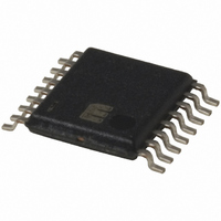
MIC2584-JBTS Micrel Inc, MIC2584-JBTS Datasheet - Page 18

MIC2584-JBTS
Manufacturer Part Number
MIC2584-JBTS
Description
IC CTRLR HOT SWAP DUAL 16-TSSOP
Manufacturer
Micrel Inc
Type
Hot-Swap Controllerr
Datasheet
1.MIC2584-JYTS.pdf
(28 pages)
Specifications of MIC2584-JBTS
Applications
General Purpose
Internal Switch(s)
No
Voltage - Supply
1 V ~ 13.2 V
Operating Temperature
-40°C ~ 85°C
Mounting Type
Surface Mount
Package / Case
16-TSSOP
Linear Misc Type
Positive Low Voltage
Family Name
MIC2584
Package Type
TSSOP
Operating Supply Voltage (min)
1V
Operating Supply Voltage (max)
13.2V
Operating Temperature (min)
-40C
Operating Temperature (max)
85C
Operating Temperature Classification
Industrial
Product Depth (mm)
4.4mm
Product Height (mm)
0.9mm
Product Length (mm)
5mm
Mounting
Surface Mount
Pin Count
16
Lead Free Status / RoHS Status
Contains lead / RoHS non-compliant
Available stocks
Company
Part Number
Manufacturer
Quantity
Price
Company:
Part Number:
MIC2584-JBTS
Manufacturer:
MIC
Quantity:
23
Company:
Part Number:
MIC2584-JBTS
Manufacturer:
MICREL
Quantity:
240
Part Number:
MIC2584-JBTS
Manufacturer:
MICREL/麦瑞
Quantity:
20 000
MIC2584/2585
Applications Information
Output Tracking and Sequencing
The MIC2585 is equipped with optional supply
settings: Tracking or Sequencing. There are many applica-
tions that require two supplies to track one another within a
specified maximum potential difference (or time) during power-
up and power-down, such as in switching a processor on and
off. In many other systems and applications, supply sequenc-
ing during turn-on may be essential such as when a specific
circuit block (e.g., a system clock) requires available power
before another block of system circuitry. For either supply
configuration, the MIC2585 requires only one additional
component and can be used as an integrated solution to
traditional, and most often complex, discrete circuit solutions.
Additionally, the two optional supply settings may be com-
bined to provide supply sequencing during start-up and
supply tracking during turn-off (see Figure 6 below). The
MIC2585 guarantees supply tracking within 250mV for power-
MIC2584/2585
1.8V
V
V
5V
IN1
IN2
0.01 F
R1
47k
(8V)
(6V)
*D1
*D2
Undervoltage (OUT1) = 4.4V
Undervoltage (OUT2) = 1.5V
Circuit Breaker Response Time = 5ms
Sequenced Output Delay = 20ms
*Diodes are BZX84C(x)V(x)
**Si4922DY is a dual Power MOSFET
Additional pins omitted for clarity
C5
0.1 F
C6
11
12
C1
1 F
C2
1 F
8
Figure 6. Output Sequencing/Tracking Combination
ON
CFILTER
CDLY
VCC1
3
24
1
R
0.007
SENSE1
5%
SENSE1
4
23
MIC2585-1
GND
13
VCC2
3
1
1
R
0.015
SENSE2
5%
SENSE2
18
2
GATE2
GATE1
4
OUT2
OUT1
2
TRK
up and power-down independent of the load capacitance of
each supply. See "
Wiring the TRK pin to either OUT1 or OUT2 of the MIC2585
enables the tracking feature. The OUT1 and OUT2 pins
provide output track sensing and are wired directly to the
output (source) of the external MOSFET for Channel 1 and
Channel 2, respectively.
The MIC2584/85 can also be used in systems that support
more than two supplies. Figure 7 illustrates the generic use
of two separate controllers configured to support four inde-
pendent supply rails with an associated output timing re-
sponse. The PG (or /POR) output of the first controller is used
to enable the second controller. As configured, a fault condi-
tion on either V
shut down. For systems with multiple power sequencing
requirements, the controllers’ output tracking and sequenc-
ing features can be implemented in order to meet the system’s
timing demands.
FB2
FB1
0.022 F
Si4922DY (1)
(SO-8)
3
5
9
7
22
20
18
**Q2
C4
10.5k
1%
R5
0.022 F
Si4922DY (2)
8.06k
OUT1
C3
(SO-8)
1%
**Q1
R4
Figure 2
or V
OUT2
" of the "
R2
39.2k
1%
R3
15.8k
1%
will result in all channels being
C
1500 F
LOAD1
C
100 F
Timing Diagrams
LOAD2
V
5V@5A
V
1.8V@2A
OUT1
OUT2
March 2005
".
Micrel


