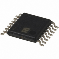
MIC2584-JBTS Micrel Inc, MIC2584-JBTS Datasheet - Page 19

MIC2584-JBTS
Manufacturer Part Number
MIC2584-JBTS
Description
IC CTRLR HOT SWAP DUAL 16-TSSOP
Manufacturer
Micrel Inc
Type
Hot-Swap Controllerr
Datasheet
1.MIC2584-JYTS.pdf
(28 pages)
Specifications of MIC2584-JBTS
Applications
General Purpose
Internal Switch(s)
No
Voltage - Supply
1 V ~ 13.2 V
Operating Temperature
-40°C ~ 85°C
Mounting Type
Surface Mount
Package / Case
16-TSSOP
Linear Misc Type
Positive Low Voltage
Family Name
MIC2584
Package Type
TSSOP
Operating Supply Voltage (min)
1V
Operating Supply Voltage (max)
13.2V
Operating Temperature (min)
-40C
Operating Temperature (max)
85C
Operating Temperature Classification
Industrial
Product Depth (mm)
4.4mm
Product Height (mm)
0.9mm
Product Length (mm)
5mm
Mounting
Surface Mount
Pin Count
16
Lead Free Status / RoHS Status
Contains lead / RoHS non-compliant
Available stocks
Company
Part Number
Manufacturer
Quantity
Price
Company:
Part Number:
MIC2584-JBTS
Manufacturer:
MIC
Quantity:
23
Company:
Part Number:
MIC2584-JBTS
Manufacturer:
MICREL
Quantity:
240
Part Number:
MIC2584-JBTS
Manufacturer:
MICREL/麦瑞
Quantity:
20 000
Fast Output Discharge for Capacitive Loads
In many applications where a switch controller is turned off by
either removing the PCB from the backplane or the ON pin is
reset, capacitive loading will cause the output to retain
voltage unless a ‘bleed’ (low impedance) path is in place in
order to discharge the capacitance. The MIC2585 is equipped
with an internal MOSFET that allows the discharging of any
load capacitance to ground through a 50 to 170 path. The
discharge feature is configured by wiring the DIS pin to the
output (source) of the external MOSFET and is enabled if the
TRK pin is below 0.3V after the controller has been disabled
by a logic low signal received at the ON pin of Figure 1. See
the "
is required from DIS to V
25mA for the DIS pin is not exceeded.
March 2005
MIC2584/2585
Typical Application
EN
" circuit of Figure 1. A series resistor
ON
/FAULT
PG
ON
/FAULT
OUT
MIC2585
MIC2585
GATE1
GATE2
GATE1
GATE2
OUT1
OUT2
OUT1
OUT2
so that the maximum current of
Figure 7. Supporting More Than Two Supplies
V
V
IN1
IN3
V
V
IN2
IN4
V
V
V
V
OUT1
OUT2
OUT3
OUT4
V
V
OUT1
OUT3
/FAULT
/V
/V
19
OUT2
OUT4
ON
PG
Output Turn-Off Sequencing - No Tracking
There are many applications where it is necessary or desir-
able for the supply rails to sequence during turn-on and turn-
off, as is the case with some microprocessor requirements.
The MIC2585 can be configured to allow one output to shut
off first, followed by the other output. Figure 8 illustrates an
example circuit that sequences OUT1 and OUT2 in a first on–
last off application. During start-up, capacitor C
V
pin receives a low signal by removing the PCB from the
backplane, or by an external processor signal, DIS1 and DIS2
will assert low. The external crowbar circuit connected from
the DIS2 pin will immediately bring V
V
external, 70 internal) series path.
OUT1
OUT1
to turn on followed by V
will discharge to ground through the 750
System Timing
Short Circuit
on V
OUT1
OUT2
20ms later. Once the ON
OUT2
to ground while
MIC2584/2585
DLY
allows for
(680
Micrel


