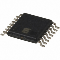
MIC2584-JBTS Micrel Inc, MIC2584-JBTS Datasheet - Page 23

MIC2584-JBTS
Manufacturer Part Number
MIC2584-JBTS
Description
IC CTRLR HOT SWAP DUAL 16-TSSOP
Manufacturer
Micrel Inc
Type
Hot-Swap Controllerr
Datasheet
1.MIC2584-JYTS.pdf
(28 pages)
Specifications of MIC2584-JBTS
Applications
General Purpose
Internal Switch(s)
No
Voltage - Supply
1 V ~ 13.2 V
Operating Temperature
-40°C ~ 85°C
Mounting Type
Surface Mount
Package / Case
16-TSSOP
Linear Misc Type
Positive Low Voltage
Family Name
MIC2584
Package Type
TSSOP
Operating Supply Voltage (min)
1V
Operating Supply Voltage (max)
13.2V
Operating Temperature (min)
-40C
Operating Temperature (max)
85C
Operating Temperature Classification
Industrial
Product Depth (mm)
4.4mm
Product Height (mm)
0.9mm
Product Length (mm)
5mm
Mounting
Surface Mount
Pin Count
16
Lead Free Status / RoHS Status
Contains lead / RoHS non-compliant
Available stocks
Company
Part Number
Manufacturer
Quantity
Price
Company:
Part Number:
MIC2584-JBTS
Manufacturer:
MIC
Quantity:
23
Company:
Part Number:
MIC2584-JBTS
Manufacturer:
MICREL
Quantity:
240
Part Number:
MIC2584-JBTS
Manufacturer:
MICREL/麦瑞
Quantity:
20 000
the opposite direction. Here, the worst-case maximum cur-
rent is found using a 57.5mV trip voltage and a sense resistor
that is 3% low in value. The resulting equation is:
As an example, if an output must carry a continuous 6A
without nuisance trips occurring, Equation 11
yields:
standard value is 6m . At the other set of tolerance extremes
for the output in question,
tum, we can determine the necessary wattage of the sense
resistor using P = I
R will be (0.97)(R
following: P
ample, a 1W sense resistor is sufficient.
MOSFET Selection
Selecting the proper external MOSFET for use with the
MIC2584/85 involves three straightforward tasks:
March 2005
MIC2584/2585
I
I
LOAD(CONT,MAX)
LOAD(CONT,MAX)
• Choice of a MOSFET which meets minimum
• Selection of a device to handle the maximum
• Verify the selected part’s ability to withstand any
voltage requirements.
continuous current (steady-state thermal is-
sues).
peak currents (transient thermal issues).
R
SENSE(MAX)
MAX
= (9.88A)
0.97 R
2
SENSE(NOM)
59.3mV
6.0m
R, where I will be I
CORE SUPPLY
41.3mV
57.5mV
CORE
(V
SENSE(NOM)
6A
2
CC
(5.82m ) = 0.568W. In this ex-
)
9 88
). These numbers yield the
.
6 88
A
.
Dual Supply DSP
Data Out
. Knowing this final da-
Data In
Bus Control
m
External
Figure 11. Bidirectional Port Bus Contention
OE
LOAD(CONT, MAX)
R
SENSE(NOM)
. The next lowest
59.3mV
I/O
OUTPUT
CIRCUIT
DRIVER
BLOCK
(12)
, and
V
DD
23
MOSFET Voltage Requirements
The first voltage requirement for the MOSFET is easily stated:
the drain-source breakdown voltage of the MOSFET must be
greater than V
ably be expected to see high-frequency transients as high as
18V. Therefore, the drain-source breakdown voltage of the
MOSFET must be at least 19V. For ample safety margin and
standard availability, the closest minimum value will be 20V.
The second breakdown voltage criterion that must be met is a
bit subtler than simple drain-source breakdown voltage, but is
not hard to meet. In MIC2584/85 applications, the gate of the
external MOSFET is driven up to approximately 20V by the
internal output MOSFET (again, assuming 12V operation). At
the same time, if the output of the external MOSFET (its source)
is suddenly subjected to a short, the gate-source voltage will go
to (20V – 0V) = 20V. This means that the external MOSFET
must be chosen to have a gate-source breakdown voltage of
20V or more, which is an available standard maximum value.
However, if operation is above 12V, the 20V gate-source
maximum will likely be exceeded. As a result, an external Zener
diode clamp should be used to prevent breakdown of the
external MOSFET when operating at voltages above 10V. A
Zener diode with 10V rating is recommended as shown in
Figure 12. At the present time, most power MOSFETs with a
20V gate-source voltage rating have a 30V drain-source break-
down rating or higher. As a general tip, choose surface-mount
devices with a drain-source rating of 30V as a starting point.
Finally, the external gate drive of the MIC2584/85 requires a
low-voltage logic level MOSFET when operating at voltages
lower than 3V. There are 2.5V logic level MOSFETs available.
See Table 5, "
suggested manufacturers.
I/O SUPPLY
TX_/RX
(V
DD
I
I
1
2
)
IN(MAX)
MOSFET and Sense Resistor Vendors
V
DD
. For instance, a 12V input may reason-
Peripheral
OUTPUT
CIRCUIT
DRIVER
BLOCK
Data Out
Data In
OE
MIC2584/2585
Micrel
" for


