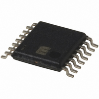
MIC2584-JBTS Micrel Inc, MIC2584-JBTS Datasheet - Page 3

MIC2584-JBTS
Manufacturer Part Number
MIC2584-JBTS
Description
IC CTRLR HOT SWAP DUAL 16-TSSOP
Manufacturer
Micrel Inc
Type
Hot-Swap Controllerr
Datasheet
1.MIC2584-JYTS.pdf
(28 pages)
Specifications of MIC2584-JBTS
Applications
General Purpose
Internal Switch(s)
No
Voltage - Supply
1 V ~ 13.2 V
Operating Temperature
-40°C ~ 85°C
Mounting Type
Surface Mount
Package / Case
16-TSSOP
Linear Misc Type
Positive Low Voltage
Family Name
MIC2584
Package Type
TSSOP
Operating Supply Voltage (min)
1V
Operating Supply Voltage (max)
13.2V
Operating Temperature (min)
-40C
Operating Temperature (max)
85C
Operating Temperature Classification
Industrial
Product Depth (mm)
4.4mm
Product Height (mm)
0.9mm
Product Length (mm)
5mm
Mounting
Surface Mount
Pin Count
16
Lead Free Status / RoHS Status
Contains lead / RoHS non-compliant
Available stocks
Company
Part Number
Manufacturer
Quantity
Price
Company:
Part Number:
MIC2584-JBTS
Manufacturer:
MIC
Quantity:
23
Company:
Part Number:
MIC2584-JBTS
Manufacturer:
MICREL
Quantity:
240
Part Number:
MIC2584-JBTS
Manufacturer:
MICREL/麦瑞
Quantity:
20 000
Pin Configuration
Pin Description
March 2005
MIC2584/2585
Pin Number
MIC2584
2, 15
16
1
6
CFILTER
SENSE2
GATE2
CPOR
VCC2
OUT2
Pin Number
FB2
ON
MIC2585
16-Pin TSSOP (TS)
2, 23
24
1
8
1
2
3
4
5
6
7
8
MIC2584
SENSE2, SENSE1
Pin Name
VCC1
VCC2
16 VCC1
15
14
13
12
11
10
9
ON
SENSE1
GATE1
OUT1
FB1
/POR
/FAULT
GND
Pin Function
Positive Supply (Input), Channel 1: This input is the main supply to the
internal circuitry and must be in the range of 2.3V to 13.2V. The GATE1 pin
is held low by an internal undervoltage lockout circuit until V
exceed their respective undervoltage lockout threshold of 2.165V and 0.8V.
This input is protected up to 20V.
Positive Supply (Input), Channel 2: The GATE2 pin is held low by an
internal undervoltage lockout circuit until V
respective undervoltage lockout threshold of 2.165V and 0.8V. This input
must be in the range of 1.0V to 13.2V and less than or equal to V
input is protected up to 20V.
Circuit Breaker Sense (Inputs): A resistor between this pin and VCC1 and
VCC2 sets the current limit threshold for each channel. Whenever the
voltage across either sense resistor exceeds the slow trip current limit
threshold (V
load current. If V
t
immediately pulled low. If the voltage across either sense resistor exceeds
the fast trip circuit breaker threshold, V
high amplitude power supply faults, then both GATE outputs are immediately
brought low without delay. To disable the circuit breaker for either channel,
the SENSE and VCC pins can be tied together.
The default V
are available: 150mV, 200mV, or OFF (V
factory for availability of other options.
Enable (Input): Active High. The ON pin, an input to a Schmitt-triggered
comparator used to enable/disable the controller, is compared to a 1.235V
reference with 25mV of hysteresis. When a logic high is applied to the ON
pin (V
GATE2 pins begin ramping up towards their final operating voltage. When
the ON pin receives a logic low signal (V
grounded and /FAULT remains high if both inputs are above their respective
UVLO thresholds. The ON pin must be low for at least 20 s in order to
initiate a start-up sequence. Additionally, toggling the ON pin LOW to HIGH
resets the circuit breaker.
OCSLOW
ON
, then the circuit breaker is tripped and both GATE outputs are
> 1.235V), a start-up sequence begins when the GATE1 and
3
TRIPSLOW
TRIPFAST
TRIPSLOW
), the GATE voltage is adjusted to ensure a constant
for either device is 100mV. Other fast trip thresholds
CFILTER
SENSE2
GATE2
(50mV) is exceeded for longer than time period
CPOR
VCC2
OUT2
CDLY
DIS2
OV2
TRK
FB2
ON
10
11
12
1
2
3
4
5
6
7
8
9
24-Pin TSSOP (TS)
TRIPFAST
ON
TRIPFAST
MIC2585
CC1
< 1.21V), the GATE pins are
and V
, at any point due to fast,
disabled). Please contact
CC2
exceed their
24 VCC1
23
22
21
20
19
18
17
16
15
14
13
CC1
SENSE1
GATE1
OV1
OUT1
DIS1
FB1
PG1
PG2
/POR
/FAULT
GND
MIC2584/2585
and V
CC1
. This
CC2
Micrel


