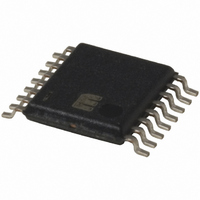
MIC2584-JBTS Micrel Inc, MIC2584-JBTS Datasheet - Page 7

MIC2584-JBTS
Manufacturer Part Number
MIC2584-JBTS
Description
IC CTRLR HOT SWAP DUAL 16-TSSOP
Manufacturer
Micrel Inc
Type
Hot-Swap Controllerr
Datasheet
1.MIC2584-JYTS.pdf
(28 pages)
Specifications of MIC2584-JBTS
Applications
General Purpose
Internal Switch(s)
No
Voltage - Supply
1 V ~ 13.2 V
Operating Temperature
-40°C ~ 85°C
Mounting Type
Surface Mount
Package / Case
16-TSSOP
Linear Misc Type
Positive Low Voltage
Family Name
MIC2584
Package Type
TSSOP
Operating Supply Voltage (min)
1V
Operating Supply Voltage (max)
13.2V
Operating Temperature (min)
-40C
Operating Temperature (max)
85C
Operating Temperature Classification
Industrial
Product Depth (mm)
4.4mm
Product Height (mm)
0.9mm
Product Length (mm)
5mm
Mounting
Surface Mount
Pin Count
16
Lead Free Status / RoHS Status
Contains lead / RoHS non-compliant
Available stocks
Company
Part Number
Manufacturer
Quantity
Price
Company:
Part Number:
MIC2584-JBTS
Manufacturer:
MIC
Quantity:
23
Company:
Part Number:
MIC2584-JBTS
Manufacturer:
MICREL
Quantity:
240
Part Number:
MIC2584-JBTS
Manufacturer:
MICREL/麦瑞
Quantity:
20 000
Symbol
I
V
V
V
V
V
V
V
V
V
V
V
V
V
I
V
V
V
V
I
V
I
V
AC Parameters
t
t
Note 1.
Note 2.
Note 3.
Note 4.
March 2005
MIC2584/2585
CPOR
DELAY
ON
PULLUP
OCFAST
OCSLOW
POR
PORHYS
START
TRK
TRKOFF
FB1
FB1HYS
FB2
FB2HYS
OV1
OV1HYS
OV2
OV2HYS
DELAY
DLYHYS
ON
ONHYS
OL
GATEWIN
Exceeding the absolute maximum rating may damage the device.
The device is not guaranteed to function outside its operating rating.
For the MIC2584, V
Specification for packaged product only.
Parameter
Power-on Reset Current
Power-on Reset Delay Threshold
Power-on Reset Delay Threshold
Hysteresis
Start-up Threshold
TRK Pin Threshold
(MIC2585 only)
TRK Pin Turn-off Voltage
(MIC2585 only)
FB1 Threshold
FB1 Threshold Hysteresis
FB2 Threshold
FB2 Threshold Hysteresis
OV1 Threshold
(MIC2585 only)
OV1 Threshold Hysteresis
(MIC2585 only)
OV2 Threshold
(MIC2585 only)
OV2 Threshold Hysteresis
(MIC2585 only)
Delay Timer Pin Current
(MIC2585 only)
Delay Timer Pin Threshold
(MIC2585 only)
Delay Timer Pin Threshold
Hysteresis (MIC2585 only)
ON Pin Input Threshold
ON Pin Hysteresis
ON Pin Input Current
/FAULT , /POR , PG1, PG2 Output
Low Voltage (PG1 and PG2 for
MIC2585 only)
/FAULT , /POR , PG1, PG2 Active
Output Pull-up Current
(PG1 and PG2 for MIC2585 only)
GATE1 and GATE2 ON/OFF
Voltage Window (Tracking enabled)
Note 3
Fast Overcurrent Sense to GATE
Low Trip Time
Slow Overcurrent Sense to GATE
Low Trip Time
GATEWIN
is specified only when ON is asserted.
Condition
V
Start-up cycle
Start-up cycle
ON deasserted, I
V
ON asserted, V
V
V
V
I
ON asserted, V
/POR = V
See Timing Diagram (Figure 2)
V
See Timing Diagram (Figure 3)
V
OUT
CC1
CC1
CC1
CC1
ON
CCx
CCx
= V
= 1.6mA, V
= 5V, C
= V
= V
= V
– V
– V
CCX
SENSEx
SENSEx
CC2
CC2
CC2
CC1
7
POR
= 5V
= 5V
= 5V
– 1V
SENSE2
FB1
CC1
= 100mV, C
= 50mV, C
GATE
= 0.5V
> 1.25V, V
Timer discharge current
= 5V
> 10 A
– V
Timer charge current
OUT2
FILTER
GATE
Charge current
FB2
Sink current
> 0.8V
= 10nF
= 0
1.190
1.190
1.190
1.190
1.190
–3.5
0.25
0.25
0.75
0.75
Min
150
–9
7
1.235
1.235
1.235
1.235
1.235
–2.5
0.30
0.30
0.80
0.80
Typ
200
100
250
2.5
0.1
25
25
25
25
25
–6
25
25
12
20
1
MIC2584/2585
1.290
1.290
1.290
1.290
1.290
Max
–1.5
0.35
0.35
0.85
0.85
400
250
0.5
0.4
–3
22
Micrel
Units
mV
mV
mV
mV
mV
mV
mV
mV
mV
V
V
V
V
V
V
V
V
V
V
A
A
A
A
s
s


