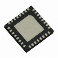
IR3503MTRPBF International Rectifier, IR3503MTRPBF Datasheet - Page 21

IR3503MTRPBF
Manufacturer Part Number
IR3503MTRPBF
Description
IC CTRL XPHASE VR11.0/1 32-MLPQ
Manufacturer
International Rectifier
Series
XPhase3™r
Datasheet
1.IR3503MTRPBF.pdf
(39 pages)
Specifications of IR3503MTRPBF
Applications
Processor
Current - Supply
8mA
Voltage - Supply
4.75 V ~ 7.5 V
Operating Temperature
0°C ~ 100°C
Mounting Type
Surface Mount
Package / Case
*
Package
32-Lead MLPQ
Circuit
X-Phase Control IC
Switch Freq (khz)
250kHz to 1.5MHz
Pbf
PbF Option Available
Lead Free Status / RoHS Status
Lead free / RoHS Compliant
Other names
IR3503MTRPBFTR
at 1.03V in order to facilitate direct interfacing with the CPU.
Power State Indicator (PSI#)
PSI# is an active low input logic signal to IR3503 sent by the CPU. The PSI# signal will be asserted (low) whenever
the CPU enters low power state. IR3503 uses this signal to improve the efficiency of the voltage regulator (VR) by
turning off a few phases under light load conditions. A single PSI# bus is hard wired to all the phase ICs. Once,
PSI# is asserted (low), IR3503 waits for 7 CLKOUT cycles and then registers the active number of phases at that
instant. The phase IC (IR3529) waits for 8 PHSIN cycles after PSI# assertion to shut the phase off and then issues
a down SHIFT signal. On PSI# de-assertion, IR3503 cranks the CLKOUT frequency (corresponding to the number
of phases active before PSI# assertion) once it receives an up SHIFT signal from the phase ICs. The first phase in
the daisy chain should be always on during PSI mode of operation. The system design should also ensure that the
VR is not forced into PSI mode of operation within 8 switching cycles after a phase shed event.
SHIFT Signal Implementation:
The SHIFT function is used to communicate the status change of the phase ICs in order to improve the daisy chain
timing. The main objective is to minimize the output voltage deviation when phases are taken into or out of the daisy
chain loop. The SHIFT signal rides on
(insertion of phases) and is pulled down to LGND to indicate a down shift in CLK frequency (phase shedding
operation). Changes in the number of phases in the system may occur due to the following operations:
•
•
•
respect to the load current can be adjusted with the resistors RTCMP2 and RTCMP3. The IMON signal is clamped
Active or Dynamic Shedding: This is a post-power up event when phases are shut down based on the load
requirements. Such an operation will lead to perturbations in the output voltage.
Static Shedding: This may occur prior to power supply turn-on as long as phases are not de-shed post-power
up. Since, this occurs when the power supply is turned off and hence does not affect the output voltage.
PSI# assertion or de-assertion: This is mostly a dynamic event and it will affect the output voltage. The
maximum permissible deviation in output voltage is slightly higher during such events.
Page 21 of 39
Figure 12: Current Report Signal (IMON) implementation
VDAC
+
-
VDAC
Buffer
V
CCL
2
50mV
VDRP
Control IC
200k
100k
and is pulled up to VCCL to indicate an up shift in CLK frequency
200k
200k
200k
-
+
200k
+
-
Thermal
Comp
Amplifier
VDRP
Buffer
1.03
0
+
-
VDRP
VN
DAC_BUFF
IMON
IIN
From Phase ICs
RTCMP1
RTCMP2
RTCMP3
RTHERM
February 12, 2010
IR3503


