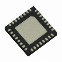
IR3503MTRPBF International Rectifier, IR3503MTRPBF Datasheet - Page 29

IR3503MTRPBF
Manufacturer Part Number
IR3503MTRPBF
Description
IC CTRL XPHASE VR11.0/1 32-MLPQ
Manufacturer
International Rectifier
Series
XPhase3™r
Datasheet
1.IR3503MTRPBF.pdf
(39 pages)
Specifications of IR3503MTRPBF
Applications
Processor
Current - Supply
8mA
Voltage - Supply
4.75 V ~ 7.5 V
Operating Temperature
0°C ~ 100°C
Mounting Type
Surface Mount
Package / Case
*
Package
32-Lead MLPQ
Circuit
X-Phase Control IC
Switch Freq (khz)
250kHz to 1.5MHz
Pbf
PbF Option Available
Lead Free Status / RoHS Status
Lead free / RoHS Compliant
Other names
IR3503MTRPBFTR
The soft start delay time (TD1) and VR ready delay time (TD3) are determined by (8) to (9) respectively.
Once C
VDAC Slew Rate Programming Capacitor C
The slew rate of VDAC slope SR
where I
The resistor R
Current Report Gain and Thermal Compensation
Intel VR11.1 specifications require IMON to report the core maximum load current of the CPU be reported as 1 V
nominal. The core maximum current can be different for different platforms. The IMON tuning resistors can
therefore be adjusted and thermally compensated to adjust the load current gain with respect to the IMON. The
expressions that govern the relationship between load current, IMON, and VDRP at room temperature are given
by
The change in inductor DCR with temperature is compensated by an equivalent variation in the RTHERM. The
following equations derive the R
SINK
SS/DEL
Page 29 of 39
is the sink current of VDAC pin. The slew rate of VDAC up-slope is the same as that of down-slope.
VDAC
is chosen, the minimum over-current fault latch delay time
is used to compensate VDAC circuit and can be calculated as follows
VDRP
K
THERM
=
IMON
VDAC
t
OCDEL
TD
C
R
SS
_
TCMP1
L
room
3
/
_
=
DOWN
DEL
=
MAX
+
1
3
=
C
1
3
=
C
R
and R
⋅
=
TD
SS
C
⋅
VDAC
VDAC
=
I
can be programmed by the external capacitor C
R
TD
/
1
SS
o
R
1
DEL
L
V
max
R
L
I
=
/
_
2
DEL
_
room
TCMP2
I
DISCHG
L
=
V
=
room
*
C
CHG
*
n
_
O
,
n
SR
I
SS
4 (
VDAC
room
K
2
CHG
*
⋅
I
0 .
⋅
G
/
I
⋅
SINK
c
DOWN
G
DEL
. 0
CHG
if R
π
_
cs
−
∗
cs
room
12
=
V
⋅
⋅
and Resistor R
1 [
1 *
⋅
900
TCMP3
O
TD
)
+
=
=
1
4 .
=
1
=
+
2
3850
44
+
SR
kHz
(
C
1
=
*
(
R
C
and the thermistor (R
(
RTCMP
52
SS
*
C
DOWN
RTCMP
V
SS
L
55
10
52
SS
O
_
/
5 .
⋅
/
DEL
room
52
DEL
C
5 .
*
/
−
*
*
DEL
6
n
10
10
VDAC
10
*
5 .
10
*
⋅
*
*
−
) 3
G
1 *
) 3
−
−
. 0
6
4 (
10
−
6
6
VDAC
II
6
cs
II
4 .
0 .
12
∗
−
(
)
(
6
(
−
RTCMP
RTCMP
T
,
V
t
L
K
OCDEL
O
RTCMP
RTCMP
_
)
c
MAX
_
t
max
1
1
is fixed and can be quantified as
THERM
+
+
−
RTHERM
RTHERM
3
3
=
T
room
(
R
and β
L
February 12, 2010
)]
_
max
VDAC
n
THERM
_
_
⋅
room
G
room
as defined in (11),
cs
IR3503
) are fixed.
)
)
)
⋅
⋅
I
I
o
o
(13)
(14)
(15)
(16)
(10)
(11)
(12)
(7)
(8)
(9)


