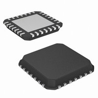
ISL6537ACR Intersil, ISL6537ACR Datasheet - Page 6

ISL6537ACR
Manufacturer Part Number
ISL6537ACR
Description
IC REG/CTRLR ACPI DUAL DDR 28QFN
Manufacturer
Intersil
Datasheet
1.ISL6537ACRZ-T.pdf
(16 pages)
Specifications of ISL6537ACR
Applications
Memory, DDR/DDR2 Regulator
Current - Supply
7mA
Operating Temperature
0°C ~ 70°C
Mounting Type
Surface Mount
Package / Case
28-QFN
Lead Free Status / RoHS Status
Contains lead / RoHS non-compliant
Voltage - Supply
-
Available stocks
Company
Part Number
Manufacturer
Quantity
Price
Company:
Part Number:
ISL6537ACR
Manufacturer:
Intersil
Quantity:
800
Part Number:
ISL6537ACR
Manufacturer:
INTERSIL
Quantity:
20 000
Company:
Part Number:
ISL6537ACR-TR
Manufacturer:
PHI
Quantity:
12
Company:
Part Number:
ISL6537ACRTR5160
Manufacturer:
INTERSIL
Quantity:
7 412
Company:
Part Number:
ISL6537ACRZ
Manufacturer:
Intersil
Quantity:
500
Part Number:
ISL6537ACRZ
Manufacturer:
INTERSIL
Quantity:
20 000
Part Number:
ISL6537ACRZ-T
Manufacturer:
INTERSIL
Quantity:
20 000
Company:
Part Number:
ISL6537ACRZ-TR5160
Manufacturer:
REALTEK
Quantity:
6 600
Part Number:
ISL6537ACRZ-TR5160
Manufacturer:
INTERSIL
Quantity:
20 000
Electrical Specifications
NOTE:
Functional Pin Description
5VSBY (Pin 1)
5VSBY is the bias supply of the ISL6537A. It is typically
connected to the 5V standby rail of an ATX power supply.
During S4/S5 sleep states the ISL6537A enters a reduced
power mode and draws less than 1mA (I
5VSBY supply. The supply to 5VSBY should be locally
bypassed using a 0.1μF capacitor.
PWM CONTROLLER GATE DRIVERS
UGATE and LGATE Source
UGATE and LGATE Sink
VTT REGULATOR
Upper Divider Impedance
Lower Divider Impedance
VREF_OUT Buffer Source Current
Maximum V
LINEAR REGULATORS
DC Gain
Gain Bandwidth Product
Slew Rate
DRIVEn High Output Voltage
DRIVEn Low Output Voltage
DRIVEn High Output Source Current
DRIVEn Low Output Sink Current
VIDPGD
V
V
PROTECTION
OCSET Current Source
V
V
V
V
V
V
V
Thermal Shutdown Limit
3. Limits should be considered typical and are not production tested
TT_GMCH/CPU
TT_GMCH/CPU
TT_DDR
DDQ
DDQ
TT_DDR
TT_DDR
GMCH
TT_GMCH/CPU
OV Level
UV Level
UV Level
Current Limit
OV Level
UV Level
TT
Load Current
PARAMETER
Rising Threshold
Falling Threshold
UV Level
6
Recommended Operating Conditions, Unless Otherwise Noted. Refer to Block and Simplified Power System
Diagrams and Typical Application Schematics (Continued)
CC_S5
V
V
I
TT
TT
V
V
VREF_OUT
V
V
I
SYMBOL
VTT_MAX
FB4
FB2
I
FB
FB
GBWP
/V
/V
OCSET
I
I
GATE
GATE
T
R
SR
R
VREF_IN
VREF_IN
) from the
/V
/V
SD
/V
/V
U
L
REF
REF
REF
REF
Periodic load applied with 30% duty cycle and
10ms period using ISL6537A_6506EVAL1
evaluation board (see Application Note AN1124)
(Note 3)
(Note 3)
(Note 3)
DRIVEn Unloaded
V
V
S0
S0
(Note 3)
S0/S3
S0/S3
S0
S0
S0
S0
(Note 3)
FB
FB
ISL6537A
= 770mV, V
= 830mV, V
TEST CONDITIONS
P12V (Pin 3)
The V
powered by P12V. P12V is not required during S3/S4/S5
operation. P12V is typically connected to the +12V rail of an
ATX power supply.
GND (Pins 4, 27, 29)
The GND terminals of the ISL6537A provide the return path
for the V
DRIVEn
DRIVEn
TT
= 0V
= 10V
TT
regulation circuit and the Linear Drivers are
LDO, and switching MOSFET gate drivers. High
9.75
.725
MIN
-3.3
15
18
-3
-
-
-
-
-
-
-
-
-
-
-
-
-
-
-
-
-
-
0.700 0.715
TYP
10.0
0.16
1.20
.740
-0.8
140
115
115
0.8
2.5
2.5
1.7
80
20
75
85
75
75
6
-
-
-
-
MAX
0.50
3.3
22
2
3
-
-
-
-
-
-
-
-
-
-
-
-
-
-
-
-
-
-
UNITS
MHz
V/μs
FN9143.5
mA
mA
mA
kΩ
kΩ
dB
μA
°C
%
%
%
%
%
%
A
A
A
V
V
V
V
A


