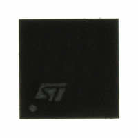
PM6685 STMicroelectronics, PM6685 Datasheet - Page 25

PM6685
Manufacturer Part Number
PM6685
Description
IC CTLR DUAL SYNC STDN 5X5VFQFPN
Manufacturer
STMicroelectronics
Specifications of PM6685
Applications
Controller, Notebook Power System
Voltage - Input
6 ~ 28 V
Number Of Outputs
2
Voltage - Output
-3.3V, 5V
Operating Temperature
0°C ~ 85°C
Mounting Type
Surface Mount
Package / Case
32-VFQFN, 32-VFQFPN
Output Voltage
5 V, 3.3 V
Output Current
0.1 A
Input Voltage
5.5 V to 28 V
Mounting Style
SMD/SMT
Maximum Operating Temperature
+ 125 C
Minimum Operating Temperature
- 10 C
Lead Free Status / RoHS Status
Lead free / RoHS Compliant
Available stocks
Company
Part Number
Manufacturer
Quantity
Price
Company:
Part Number:
PM6685
Manufacturer:
RENESAS
Quantity:
1 370
Part Number:
PM6685
Manufacturer:
ST
Quantity:
20 000
Part Number:
PM6685TR
Manufacturer:
ST
Quantity:
20 000
PM6685
7.7
The valley current limit can be set with resistor R
Equation 6
Where I
Consider the temperature effect and the worst case value in R
The accuracy of the valley current threshold detection depends on the offset of the internal
comparator (ΔV
Equation 7
Where RSNS is the sensing element (R
PM6685 provides also a fixed negative peak current limit to prevent an excessive reverse
inductor current when the switching section sinks current from the load in PWM mode. This
negative current limit threshold is measured between PHASE and SGND pins, comparing
the magnitude drop on the PHASE node during the conduction time of the low side
MOSFET with an internal fixed voltage of 120 mV.
If the current is sensed on the low side MOSFET, the negative valley-current limit INEG (if
the device works in PWM mode) is given by:
Equation 8
Soft start and soft end
Each switching section is enabled separately by asserting high EN5/EN3 pins respectively.
In order to realize the soft start, at the startup the overcurrent threshold is set 25% of the
nominal value and the undervoltage protection (see related sections) is disabled. The
controller starts charging the output capacitor working in current limit. The overcurrent
threshold is increased from 25% to 100% of the nominal value with steps of 25% every 700
μs (typ.). After 2.8 ms (typ.) the undervoltage protection is enabled. The soft start time is not
programmable. A minimum capacitor C
overshoot on the output:
Equation 9
CSENSE
Δ
I
Lvalley
I
Lvalley
OFF
= 100 µA, R
) and on the accuracy of the current generator(ΔI
=
Δ
I
CSENSE
I
CSENSE
DSon
Doc ID 11674 Rev 8
+
⎡
⎢
⎣
R
C
is the drain-source on resistance of the low side switch.
R
INT
CSENSE
CSENSE
≥
I
NEG
INT
Δ
DSon
I
Lvalley
V
=
OFF
×
is required to ensure a soft start without any
4
=
I
6
R
).
CSENSE
120
uA
DSon
R
+
I
DSon
CSENSE
CSENSE
Δ
mV
2
I
×
L
I
×
Lvalley
×
100
C
:
out
⎤
⎥
⎦
+
Δ
R
DSon
R
CSENSE
CSENSE
calculation.
CSENSE
Device description
+
Δ
R
R
):
SNS
SNS
25/48


