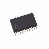
EL7571CMZ Intersil, EL7571CMZ Datasheet

EL7571CMZ
Specifications of EL7571CMZ
Related parts for EL7571CMZ
EL7571CMZ Summary of contents
Page 1
... PART NUMBER EL7571CM EL7571CM-T13 EL7571CMZ (See Note) EL7571CMZ-T13 (See Note) NOTE: Intersil Pb-free products employ special Pb-free material sets; molding compounds/die attach materials and 100% matte tin plate termination finish, which are RoHS compliant and compatible with both SnPb and Pb-free soldering operations. Intersil Pb-free products are MSL classified at Pb-free peak reflow temperatures that meet or exceed the Pb-free requirements of IPC/JEDEC J STD-020C ...
Page 2
Absolute Maximum Ratings (T = 25°C) A Supply Voltage ...
Page 3
DC Electrical Specifications T (Continued) PARAMETER DESCRIPTION I VID Input Pull up Current VID I OTEN Input Pull up Current OTEN AC Electrical Specifications T PARAMETER DESCRIPTION f Nominal Oscillator Frequency OSC f Clock Frequency CLK t Shutdown Delay OTEN ...
Page 4
Typical Performance Curves +12V Supply Sync Line Regulation 0.004 0.003 0.002 0.001 0 -0.001 -0.002 -0.003 13.5 13.0 12.5 12.0 V (V) IN +12V Supply Sync Load Regulation 0.04 0. 1.8V OUT V = 2.1V OUT 0.02 V ...
Page 5
Typical Performance Curves +5V Supply Sync with Schottky Load 2 3.5V OUT 1 2.8V OUT 0 1.8V OUT -0 1.3V OUT -1.5 -2 (A) OUT +5V ...
Page 6
Typical Performance Curves 5V Sync Transient Response 1 Efficiency vs Temperature 92.6 92.5 92.4 92.2 92.0 91.8 91.6 -45 -30 -15 0 Temperature (°C) Frequency vs Temperature 280 270 260 250 240 230 220 210 200 -45 -30 -15 0 ...
Page 7
Applications Information Circuit Description General The EL7571 is a fixed frequency, current mode, pulse width modulated (PWM) controller with an integrated high precision reference and a 5 bit Digital-to-Analog Converter (DAC). The device incorporates all the active circuitry required to ...
Page 8
Modern logic level power FET’s rapidly increase in resistivity ( their gate drive is reduced below 5V. To prevent DS-ON thermal damage to the power FET’s under load, with a reduced supply voltage, the system watchdog monitors the ...
Page 9
I = peak ripple current PEAK T = top switch on time input voltage switching frequency output voltage OUT I = minimum load MIN Since inductance value tends to decrease ...
Page 10
Input Capacitor buck converter, where the output current is greater than 10A, significant demand is placed on the input capacitor. Under steady state operation, the high side FET conducts only when it is switched “on” and ...
Page 11
MANUFACTURER MODEL MegaMos Mi4410 MegaMos Mip30N03A Siliconix Si4410 Fuji 2SK1388 IR IRF3205S Motorola MTB75N05HD Skottky Diode the non-synchronous scheme a flyback diode is required to provide a current path to the output when the high side power ...
Page 12
Voltage ID Code Output Voltage Settings V V ID4 ID3 ...
Page 13
Input, Boot-Strapped Non-Synchronous DC:DC Converter ENABLE 240pF C3 C4 220pF 1.4V C5 0.1µF POWER GOOD Voltage LD. (VID(0:4)) EL7571 5V VRM Bill of Materials - 5V Non Sync Solution COMPONENT MANUFACTURER C1 Sanyo C2 Sanyo C3 C4 C5, C6 ...
Page 14
Input Boot-Strapped Synchronous DC:DC Converter ENABLE 240pF C3 C4 220pF 1.4V C5 0.1µF POWER GOOD Voltage LD. (VID(0:4)) EL7571 5V VRM Bill of Materials - 5V Non Sync Solution COMPONENT MANUFACTURER C1 Sanyo C2 Sanyo C3 C4 C5, C6 ...
Page 15
Input, 12V Controller, Non-Sync Solution ENABLE 220pF C3 C4 220pF 1.4V C5 0.1µF POWER GOOD Voltage LD. (VID(0:4)) EL7571 5V VRM Bill of Materials - 5V Non Sync Solution COMPONENT MANUFACTURER C1 Sanyo C2 Sanyo C7, ...
Page 16
Input, 12V Controller, Synchronous DC:DC Converter ENABLE 330pF C3 C4 330pF 1.4V C5 0.1µF POWER GOOD Voltage LD. (VID(0:4)) EL7571 5V VRM Bill of Materials - 5V Input, 12V Controller Sync Solution COMPONENT MANUFACTURER C1 Sanyo C2 Sanyo C3 ...
Page 17
PCB Layout Considerations 1. Place the power MOSFET’s as close to the controller as possible. Failure will cause large amounts of ringing due to the parasitic inductance of the copper trace. Additionally, the parasitic capacitance of the ...
Page 18
EL7571 Top Layer Metal Bottom Layer Metal Top Layer Silkscreen 18 ...
Page 19
... Accordingly, the reader is cautioned to verify that data sheets are current before placing orders. Information furnished by Intersil is believed to be accurate and reliable. However, no responsibility is assumed by Intersil or its subsidiaries for its use; nor for any infringements of patents or other rights of third parties which may result from its use ...


