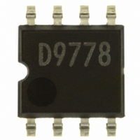
BD9778F-E2 Rohm Semiconductor, BD9778F-E2 Datasheet - Page 12

BD9778F-E2
Manufacturer Part Number
BD9778F-E2
Description
IC REG SW 2A P-CH MOSF STDN SOP8
Manufacturer
Rohm Semiconductor
Type
Step-Down (Buck)r
Specifications of BD9778F-E2
Internal Switch(s)
Yes
Synchronous Rectifier
No
Number Of Outputs
1
Voltage - Output
1 ~ 35 V
Current - Output
2A
Frequency - Switching
50kHz ~ 500kHz
Voltage - Input
7 ~ 35 V
Operating Temperature
-40°C ~ 125°C
Mounting Type
Surface Mount
Package / Case
8-SOP
Power - Output
690mW
No. Of Outputs
1
Output Voltage
35V
Output Current
2A
Voltage Regulator Case Style
SOP
No. Of Pins
8
Operating Temperature Range
-40°C To +125°C
Svhc
No SVHC (18-Jun-2010)
Base Number
9778
Input Voltage
35 V
Switching Frequency
102 KHz
Mounting Style
SMD/SMT
Lead Free Status / RoHS Status
Lead free / RoHS Compliant
Lead Free Status / RoHS Status
Lead free / RoHS Compliant, Lead free / RoHS Compliant
Other names
BD9778F-E2TR
Available stocks
Company
Part Number
Manufacturer
Quantity
Price
Company:
Part Number:
BD9778F-E2
Manufacturer:
SHARP
Quantity:
1 000
Part Number:
BD9778F-E2
Manufacturer:
ROHM/罗姆
Quantity:
20 000
2. For output capacitors having high ESR, such as electrolyte capacitor
3.
For output capacitors that have high ESR (i.e., several Ω), the phase compensation setting procedure becomes
comparatively simple. Since the DC/DC converter application has a LC resonant circuit attached to the output, a -180˚
delay to -90˚. Since the phase delay should be set within 150˚, it is a very effective method but tends to increase
the ripple component of the output voltage.
To cancel the LC resonance, the frequency to insert the phase lead should be set close to the LC resonant frequency.
The settings above have are estimated. Consequently, the settings may be adjusted on the actual system. Furthermore,
since these characteristics vary with the layout of PCB loading conditions, precise calculations should be made on the
actual system.
For output capacitors having low ESR, such as low impedance electrolyte capacitor or OS-CON
In order to use capacitors with low ESR (i.e., several tens of mΩ), two phase-leads should be inserted so that a -180˚
phase-delay, due to LC resonance, will be compensated. The following section shows a typical phase compensation
procedure.
To set phase lead frequency, insert both of the phase leads close to the LC resonant frequency. According to empirical rule,
f
phase-delay occurs in that area. If ESR component is present, however, a +90˚ phase-lead occurs to shift the phase
setting the phase lead frequency f
Z1
(3) Insert feedback resistance in the C.
(1) LC resonant circuit
(1) Phase compensation with secondary phase lead
with the R1 and C1 higher than the LC resonant frequency fr, will provide stable application conditions.
According to changes in phase characteristics, due to the ESR, only one phase lead should be inserted.
For this phase lead, select either of the methods shows below:
V
At this resonance point, a -180˚
phase-delay occurs.
O
V
O
fr =
V
R1
R2
CC
R1
R2
1
C1
L
C1
INV
INV
C
[Hz]
R3
-
-
+
Z2
A
A
C2
with R3 and C2 lower than the LC resonant frequency fr, and the phase lead frequency
V
C2
O
FB
FB
12/16
(4) Insert the R3 in integrator.
(2) With ESR provided
V
O
V
CC
A -90˚ phase-delay occurs.
L
R1
R2
R
C
ESR
INV
V
R3
O
-
A
C2
FB


