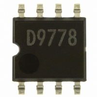
BD9778F-E2 Rohm Semiconductor, BD9778F-E2 Datasheet - Page 9

BD9778F-E2
Manufacturer Part Number
BD9778F-E2
Description
IC REG SW 2A P-CH MOSF STDN SOP8
Manufacturer
Rohm Semiconductor
Type
Step-Down (Buck)r
Specifications of BD9778F-E2
Internal Switch(s)
Yes
Synchronous Rectifier
No
Number Of Outputs
1
Voltage - Output
1 ~ 35 V
Current - Output
2A
Frequency - Switching
50kHz ~ 500kHz
Voltage - Input
7 ~ 35 V
Operating Temperature
-40°C ~ 125°C
Mounting Type
Surface Mount
Package / Case
8-SOP
Power - Output
690mW
No. Of Outputs
1
Output Voltage
35V
Output Current
2A
Voltage Regulator Case Style
SOP
No. Of Pins
8
Operating Temperature Range
-40°C To +125°C
Svhc
No SVHC (18-Jun-2010)
Base Number
9778
Input Voltage
35 V
Switching Frequency
102 KHz
Mounting Style
SMD/SMT
Lead Free Status / RoHS Status
Lead free / RoHS Compliant
Lead Free Status / RoHS Status
Lead free / RoHS Compliant, Lead free / RoHS Compliant
Other names
BD9778F-E2TR
Available stocks
Company
Part Number
Manufacturer
Quantity
Price
Company:
Part Number:
BD9778F-E2
Manufacturer:
SHARP
Quantity:
1 000
Part Number:
BD9778F-E2
Manufacturer:
ROHM/罗姆
Quantity:
20 000
2. Selection of coil (L)
3. Selection of output capacitor (Co)
1. Setting or output voltage
Description of external components
If this coil is not set to the optimum value, normal (continuous)
oscillation may not be achieved. Furthermore, set the value of
the coil with an adequate margin so that the peak current passing
through the coil will not exceed the rated current of the coil.
Set the rating of the capacitor with an adequate margin to the
output voltage. Also, set the maximum allowable ripple current
with an adequate margin to ∆IL. Furthermore, the output rise
time should be shorter than the soft start time. Select the output
capacitor having a value smaller than that obtained by the
formula shown below.
I
If this capacitance is not optimum, faulty startup may result.
( 3.5m is soft start time(min.))
Vo = Output voltage, Vin (Max.) = Maximum input voltage
Io (Max.) = Maximum load current, f = Oscillation frequency
The value of the coil can be obtained by the formula shown
below:
The output capacitor can be determined according to the
output ripple voltage ∆Vo (p-p) required.
Obtain the required ESR value by the formula shown below
and then select the capacitance.
Output voltage can be obtained by the formula shown below.
Use the formula to select the R1 and R2.
Furthermore, set the R2 to 30 kΩ or less.
Select the current passing through the R1 and R2 to be small
enough for the output current.
L
imit:2A(BD9778F/HFP,BD9001F), 4A(BD9781HFP)
L=(V
∆I
f = Operating frequency
∆Io should typically be approximately 20 to 30% of Io.
V
C
∆IL=(V
∆Vpp=∆IL x ESR+(∆IL x Vo)/(2 x Co x f x V
O
O:
Max
=1 x (1+R1/R2)
Output ripple current
IN
=
-V
IN
3.5m x (I
O
-V
) x V
O
) x V
Design procedure
O
/ (V
O
Limit
/(L x f x V
Vo
V
IN
-Io(Max))
IN
x f x ∆I
C
R
IN
T
O
)
)
C
C
in
T
C
SS
V
RT
SS
IN
IN
)
GND
Fig.30
INV
SW
FB
9/16
When Vo = 5 V and R2 = 10 kΩ ,
When I
C
When V
L=(13.2-5) x 5/13.2 x 1/100k x 1/(2 x 0.3)
=51.8μH
V
∆IL=(13.2-5) x 5/(100 x 10
IN
Max
=13.2V, Vo=5V, L=100μH, f=100kHz
C
=3.5m x (2-1)/5
=700μ
5=1 x (1+R1/10kΩ)
0.31
C
Limit
IN
Di
: 2 A, Io (Max) = 1 A, and Vo = 5V,
= 13.2 V, Vo = 5 V, Io = 2 A, and f = 100 kHz,
47μ
R
L
C
C
+
O
Calculation example
V
-6
O
R1
R2
x 100 x 10
3
x 13.2)
C
∆IL=0.31A
Max=
R1=40kΩ
L=47
700μF
μ
H


