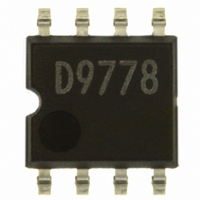
BD9778F-E2 Rohm Semiconductor, BD9778F-E2 Datasheet - Page 2

BD9778F-E2
Manufacturer Part Number
BD9778F-E2
Description
IC REG SW 2A P-CH MOSF STDN SOP8
Manufacturer
Rohm Semiconductor
Type
Step-Down (Buck)r
Specifications of BD9778F-E2
Internal Switch(s)
Yes
Synchronous Rectifier
No
Number Of Outputs
1
Voltage - Output
1 ~ 35 V
Current - Output
2A
Frequency - Switching
50kHz ~ 500kHz
Voltage - Input
7 ~ 35 V
Operating Temperature
-40°C ~ 125°C
Mounting Type
Surface Mount
Package / Case
8-SOP
Power - Output
690mW
No. Of Outputs
1
Output Voltage
35V
Output Current
2A
Voltage Regulator Case Style
SOP
No. Of Pins
8
Operating Temperature Range
-40°C To +125°C
Svhc
No SVHC (18-Jun-2010)
Base Number
9778
Input Voltage
35 V
Switching Frequency
102 KHz
Mounting Style
SMD/SMT
Lead Free Status / RoHS Status
Lead free / RoHS Compliant
Lead Free Status / RoHS Status
Lead free / RoHS Compliant, Lead free / RoHS Compliant
Other names
BD9778F-E2TR
Available stocks
Company
Part Number
Manufacturer
Quantity
Price
Company:
Part Number:
BD9778F-E2
Manufacturer:
SHARP
Quantity:
1 000
Part Number:
BD9778F-E2
Manufacturer:
ROHM/罗姆
Quantity:
20 000
Absolute Maximum Ratings(Ta = 25˚C)
Recommended operating range
Possible operating range
Electrical characteristics
BD9778F/HFP (Unless otherwise specified, Ta = -40˚C to +125˚C, V
* Not designed to be radiation-resistant.
*1 Should not exceed Pd-value.
*2 Reduce by 44mW/∞C over 25∞C, when mounted on 2-layer PCB of 70 ¥ 70 ¥ 1.6 mm3.
(PCB incorporates thermal via. Copper foil area on the front side of PCB: 10.5 ¥ 10.5 mm2. Copper foil area on the reverse side of PCB: 70 ¥ 70 mm2)
*3 Reduce by 5.52 mW/∞C over 25∞C, when mounted on 2-layer PCB of 70 ¥ 70 ¥ 1.6 mm3.
Power supply
voltage
Output switch pin voltage
Output switch current
EN/SYNC, EN pin voltage
RT, FB, INV pin voltage
Power dissipation
Operating temperature
range
Storage temperature range
Maximum junction temperature
Standby circuit current
Circuit current
[SW block]
Operating output current of overcurrent protection
Output leak current
[Error Amp block]
Reference voltage 1
Reference voltage 2
Reference voltage input regulation
Input bias current
Maximum FB voltage
Minimum FB voltage
FB sink current
FB source current
Soft start time
[Oscillator block]
Oscillation frequency
Frequency input regulation
[Enable block]
Threshold voltage
Sink current
POWER MOS FET ON resistance
Operating power supply voltage
Output switch current
Output voltage (ON Duty)
Oscillation frequency
Oscillation frequency set resistance
Operating power supply voltage
Parameter
Parameter
Parameter
Parameter
BD9778F/HFP,BD9781HFP
BD9001F
BD9778F/HFP, BD9001F
BD9781HFP
HRP7
SOP8
BD9778F/HFP,BD9781HFP
BD9001F
I
FBSOURCE
BD9778F/HFP
BD9778F/HFP
Symbol
∆V
I
I
I
FBSINK
∆F
OLIMIT
OLEAK
F
V
V
V
V
R
V
50 ~ 500
40 ~ 800
T
I
6 ~ 100
OSC
I
I
REF1
REF2
FBH
I
FBL
EN
REF
7 ~ 35
5 ~ 35
STB
Q
ON
SS
EN
B
OSC
V
~ 2
V
RT,
EN/SYNC,
Symbol
V
T
V
T
FB,
T
V
I
P
SW
jmax
0.98
0.96
-5.0
SW
Min.
opr
stg
IN
2/16
2.4
0.8
-1
70
82
d
V
-
-
-
-
-
-
-
-
-
2
INV
V
EN
Limits
Typ.
-3.0
0.53
1.00
1.00
0.05
120
102
0.5
2.5
1.7
13
-
0
3
4
0
5
1
100 ~ 800
BD9001F
BD9001F
50 ~ 300
7 ~ 48
6 ~ 100
7 ~ 48
~ 2
Max.
-0.5
1.02
1.04
0.10
170
122
IN
10
4.2
0.9
2.6
30
50
-
-
-
-
-
-
=13.2 V, V
-40 ~ +125
-40 ~ +95
-55 ~ +150
Limits
Unit
kHz
mA
mA
mS
0.69
μA
μA
μA
μA
μA
150
V
V
5.5
%
%
Ω
36
50
A
V
V
V
V
V
2
4
7
IN
IN
BD9781HFP
BD9781HFP
50 ~ 500
39 ~ 800
6 ~ 100
EN
7 ~ 35
5 ~ 35
V
I
I
* Design assurance
V
V
V
V
V
V
V
V
V
* Design assurance
V
V
R
O
SW
~ 4
EN
IN
FB
FB
IN
INV
INV
INV
FB
FB
IN
EN
T
=0A
= 5 V)
=390kΩ
Condition
=35V,V
=5 ~ 35V
=5 ~ 35V
=50mA
=V
=V
=1.5V,V
=1.5V,V
*1
*1
*2
*3
=0V,Ta=25˚C
=5V
=1.1V
=0.5V
=1.5V
INV
INV
,Ta=25˚C
EN
INV
INV
=0V
Unit
Unit
kHz
Unit
=1.5V
=0.5V
˚C
˚C
˚C
kΩ
W
%
V
V
A
V
V
A
V


