EVL250W-ATX80PL STMicroelectronics, EVL250W-ATX80PL Datasheet - Page 5
EVL250W-ATX80PL
Manufacturer Part Number
EVL250W-ATX80PL
Description
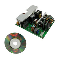
BOARD DEMO SMPS L6591/L6563S
Manufacturer
STMicroelectronics
Series
VIPer™ plusr
Datasheet
1.EVL250W-ATX80PL.pdf
(45 pages)
Specifications of EVL250W-ATX80PL
Main Purpose
Power Supply, ATX
Outputs And Type
3, Isolated
Power - Output
250W
Voltage - Output
12V, 5V, 3.3V
Current - Output
13.5A, 12A, 8A
Voltage - Input
88 ~ 264VAC
Regulator Topology
Flyback
Frequency - Switching
80kHz
Board Type
Fully Populated
Utilized Ic / Part
L6563S, L6591, L6727, VIPer27H
Input Voltage
88 VAC to 264 VAC
Output Voltage
3.3 V, 5 V, 12 V
Maximum Operating Temperature
+ 60 C
Operating Supply Voltage
80 VAC to 264 VAC
Output Power
250 W
Product
Power Management Development Tools
Lead Free Status / RoHS Status
Lead free / RoHS Compliant
For Use With/related Products
L6563S PFC controller
Other names
497-10596


AN3203
1
Main characteristics and circuit description
Here are the main characteristics of the power supply:
●
●
●
●
●
●
●
The EVL250W-ATX80PL demonstration board is made up of four main blocks, the
schematics are shown in
The front-end PFC stage is realized using a boost topology working in line modulated fixed
off time (LM-FOT) mode, described in STMicroelectronics’ application notes, AN1792;
Design of Fixed-Off-Time controlled PFC pre-regulators with the L6562 and AN3142;
Solution for designing a 400 W Fixed-Off-Time controlled PFC preregulator with the L6563S
and L6563H. The LM-FOT operation offers the advantage of having CCM operation (with
lower rms current with respect to TM mode) without the need to use a complex and
expensive controller. Therefore, it is possible to use the simple L6563S, enhanced TM PFC
controller, which integrates all the functions and protection, needed to control the stage, and
an interface with the downstream DC-DC converter.
The power stage of the PFC is realized with inductor L4, MOSFET Q1 and Q2, diode D3,
and capacitor C1. The LM-FOT operation is obtained with components D6, R15, C10, R14,
C9, R13, and Q3.
The PFC delivers a stable high voltage bus (+400 V nominal) to the downstream converters
(AHB and flyback) and provides for the reduction of the current harmonics drawn from the
mains, in order to meet the requirements of the European EN61000-3-2 norm and the
Japanese JEITA-MITI norm.
The second stage is an asymmetrical half bridge converter, driven by the L6591, a
STMicroelectronics controller dedicated to this topology. This IC integrates all the functions
Input mains range:
–
–
Outputs:
–
–
–
–
Standby consumption: < 0.2 W
Protection:
–
–
–
–
PCB type and size:
–
–
–
Safety: according to EN60950
EMI: according to EN55022 - class B
Vin: 88 ~ 264 Vrms
f: 45 ~ 66 Hz
+12 Vdc ± 2 % - 13.5 A
+5 Vdc ± 2 % - 12 A
+3.3 Vdc ± 2 % - 8 A
+5 V_SB ± 2 % - 2 A
Short-circuit
Overload
Output overvoltage
Brownout
FR4
Double side CU 70 µm
148 x 120 mm
Figure
Doc ID 17402 Rev 1
2, 3, 4, and 5.
Main characteristics and circuit description
5/45
Related parts for EVL250W-ATX80PL
Image
Part Number
Description
Manufacturer
Datasheet
Request
R

Part Number:
Description:
STMicroelectronics [RIPPLE-CARRY BINARY COUNTER/DIVIDERS]
Manufacturer:
STMicroelectronics
Datasheet:
Part Number:
Description:
STMicroelectronics [LIQUID-CRYSTAL DISPLAY DRIVERS]
Manufacturer:
STMicroelectronics
Datasheet:

Part Number:
Description:
BOARD EVAL FOR MEMS SENSORS
Manufacturer:
STMicroelectronics
Datasheet:
Part Number:
Description:
NPN TRANSISTOR POWER MODULE
Manufacturer:
STMicroelectronics
Datasheet:
Part Number:
Description:
TURBOSWITCH ULTRA-FAST HIGH VOLTAGE DIODE
Manufacturer:
STMicroelectronics
Datasheet:
Part Number:
Description:
Manufacturer:
STMicroelectronics
Datasheet:
Part Number:
Description:
DIODE / SCR MODULE
Manufacturer:
STMicroelectronics
Datasheet:
Part Number:
Description:
DIODE / SCR MODULE
Manufacturer:
STMicroelectronics
Datasheet:
Part Number:
Description:
Search -----> STE16N100
Manufacturer:
STMicroelectronics
Datasheet:
Part Number:
Description:
Search ---> STE53NA50
Manufacturer:
STMicroelectronics
Datasheet:
Part Number:
Description:
NPN Transistor Power Module
Manufacturer:
STMicroelectronics
Datasheet:
Part Number:
Description:
DIODE / SCR MODULE
Manufacturer:
STMicroelectronics
Datasheet: