HW-V5-ML555-G Xilinx Inc, HW-V5-ML555-G Datasheet - Page 79
HW-V5-ML555-G
Manufacturer Part Number
HW-V5-ML555-G
Description
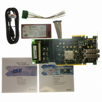
BOARD EVAL FOR VIRTEX-5 ML555
Manufacturer
Xilinx Inc
Series
Virtex™ -5r
Type
FPGAr
Datasheet
1.HW-V5-PCIE2-UNI-G.pdf
(108 pages)
Specifications of HW-V5-ML555-G
Contents
Board, Cables, CD
Silicon Manufacturer
Xilinx
Features
Parallel Connectivity, Three On-board Clock Sources
Kit Contents
Board, Cables, CD, Power Supply
Silicon Family Name
Virtex-5
Silicon Core Number
XC5VLX50T-1FF1136
Rohs Compliant
Yes
Lead Free Status / RoHS Status
Lead free / RoHS Compliant
For Use With/related Products
Virtex™-5 FPGA
For Use With
HW-AFX-SMA-SFP - CONVERSION MODULE SMA - SFPHW-AFX-SMA-SATA - CONVERSION MODULE SMA - SATAHW-AFX-SMA-RJ45 - CONVERSION MODULE SMA - RJ45HW-AFX-SMA-HSSDC2 - CONVERSION MODULE SMA - HSSDC2HW-AFX-BERG-EPHY - DAUGHTER CARD PHY BERG-EPHY
Lead Free Status / RoHS Status
Lead free / RoHS Compliant, Lead free / RoHS Compliant
Other names
122-1586
HW-V5-ML555-G
HW-V5-ML555-G
Available stocks
Company
Part Number
Manufacturer
Quantity
Price


Table 3-31: V
Virtex-5 FPGA ML555 Development Kit
UG201 (v1.4) March 10, 2008
3.3V Power to GTP Analog Supplies
PCI or PCI-X
PCI Express
and FPGA V
PCI and/or PCI-X Application Add-in Card Power Input
Power Source
R
CCINT
CCINT
1.0V Regulator
Voltage Source Selection for PCI or PCI Express Bus Applications
The SW8 switch (the source of the 3V power) must be configured according to
to generate GTP transceiver analog and FPGA V
For PCI or PCI-X applications, the host motherboard provides multiple power rails to the
add-in card as shown in
+12V from the system unit in the PCI mode. The PCI Card Electromechanical Specification
places restrictions on the amount of power an add-in card is permitted to consume from
the system unit power supply. An add-in card can consume a maximum of 25 Watts from
all power rails combined. Current values specified in
currents provided by voltage. An add-in card cannot utilize all maximum capacities and
stay under the 25W maximum specification.
Table 3-32: PCI and PCI-X Add-in Card Power Rail Capacities
Notes:
1. All values are maximum current permitted per voltage supply. Cards must still stay within 25W
maximum.
PCI or PCI-X System Unit Power Rail
Caution!
onboard +12V to +5V regulator module.
ML555 on-board 3.0V regulator
power
PCI Express system board 3.3V
power
Failure to configure SW8 and P18 properly might result in damage to the ML555
Voltage Source for FPGA V
+3.3V AUX
+3.3V
+12V
-12V
+5V
Table
www.xilinx.com
3-32. The ML555 board does not use 3.3V AUX, -12V, or
CCINT
CCINT
P11: 3V Selection Header Connections
• Slide SW8 to the OFF position,
• Slide SW8 to the ON position,
connecting pins 2 and 3. Move switch
towards silkscreen on board labeled
PCI. See
illustration.
connecting pins 1 and 2. Move switch
towards silkscreen on board labeled
PCIe. See
illustration.
Table 3-32
power.
25W Slot Maximum
Figure 3-16
Figure 3-16
375 mA
100 mA
500 mA
are maximum supply
7.6A
5.0A
Voltage Regulators
for graphic
for graphic
Table 3-31
79
Related parts for HW-V5-ML555-G
Image
Part Number
Description
Manufacturer
Datasheet
Request
R

Part Number:
Description:
EVAL PLATFORM V5 FXT
Manufacturer:
Xilinx Inc
Datasheet:

Part Number:
Description:
BOARD EVAL FOR VIRTEX-5
Manufacturer:
Xilinx Inc
Datasheet:
Part Number:
Description:
BOARD EVAL FOR VIRTEX-5
Manufacturer:
Xilinx Inc
Datasheet:

Part Number:
Description:
EVALUATION PLATFORM VIRTEX-5
Manufacturer:
Xilinx Inc
Datasheet:

Part Number:
Description:
EVALUATION PLATFORM VIRTEX-5
Manufacturer:
Xilinx Inc
Datasheet:
Part Number:
Description:
KIT DEV PCIEXPRESS GTX VIRTEX5
Manufacturer:
Xilinx Inc
Datasheet:

Part Number:
Description:
EVALUATION PLATFORM VIRTEX-5
Manufacturer:
Xilinx Inc
Datasheet:
Part Number:
Description:
BOARD EVAL FOR VIRTEX-5 ML510
Manufacturer:
Xilinx Inc
Datasheet:
Part Number:
Description:
EVALUATION PLATFORM VIRTEX-5
Manufacturer:
Xilinx Inc
Datasheet:
Part Number:
Description:
CoolRunner-II CPLD
Manufacturer:
XILINX [Xilinx, Inc]
Datasheet:
Part Number:
Description:
In-System Programmable CPLD
Manufacturer:
XILINX [Xilinx, Inc]
Datasheet:
Part Number:
Description:
High-Performance CPLD
Manufacturer:
XILINX [Xilinx, Inc]
Datasheet:
Part Number:
Description:
XCR3128XL 128 Macrocell CPLD
Manufacturer:
XILINX [Xilinx, Inc]
Datasheet:
Part Number:
Description:
XC95288XL High Performance CPLD
Manufacturer:
XILINX [Xilinx, Inc]
Datasheet: