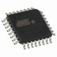
AT89LP428-20AU Atmel, AT89LP428-20AU Datasheet - Page 27

AT89LP428-20AU
Manufacturer Part Number
AT89LP428-20AU
Description
MCU 8051 4K FLASH SPI 32TQFP
Manufacturer
Atmel
Series
89LPr
Datasheet
1.AT89LP428-20AU.pdf
(149 pages)
Specifications of AT89LP428-20AU
Core Processor
8051
Core Size
8-Bit
Speed
20MHz
Connectivity
SPI, UART/USART
Peripherals
Brown-out Detect/Reset, POR, PWM, WDT
Number Of I /o
30
Program Memory Size
4KB (4K x 8)
Program Memory Type
FLASH
Eeprom Size
512 x 8
Ram Size
768 x 8
Voltage - Supply (vcc/vdd)
2.4 V ~ 5.5 V
Oscillator Type
Internal
Operating Temperature
-40°C ~ 85°C
Package / Case
32-TQFP, 32-VQFP
Processor Series
AT89x
Core
8051
3rd Party Development Tools
PK51, CA51, A51, ULINK2
Development Tools By Supplier
AT89ISP
Lead Free Status / RoHS Status
Lead free / RoHS Compliant
Data Converters
-
Lead Free Status / Rohs Status
Details
Available stocks
Company
Part Number
Manufacturer
Quantity
Price
Company:
Part Number:
AT89LP428-20AU
Manufacturer:
RFMD
Quantity:
1 240
8.2
8.2.1
3654A–MICRO–8/09
Power-down Mode
Interrupt Recovery from Power-down
Setting the Power-down (PD) bit in PCON enters Power-down mode. Power-down mode stops
the oscillator, disables the BOD and powers down the Flash memory in order to minimize power
consumption. Only the power-on circuitry will continue to draw power during Power-down. Dur-
ing Power-down, the power supply voltage may be reduced to the RAM keep-alive voltage. The
RAM contents will be retained, but the SFR contents are not guaranteed once V
reduced. Power-down may be exited by external reset, power-on reset, or certain enabled
interrupts.
Three external interrupt sources may be configured to terminate Power-down mode: external
interrupts INT0 (P3.2) and INT1 (P3.3); and the GPI. To wake up by external interrupt INT0 or
INT1, that interrupt must be enabled by setting EX0 or EX1 in IE and must be configured for
level-sensitive operation by clearing IT0 or IT1. Any GPI on Port 1 (GPI
device. The GPI pin must be enabled in GPIEN and configured for level-sensitive detection, and
EGP in IE2 must be set in order to terminate Power-down.
When terminating Power-down by an interrupt, two different wake-up modes are available.
When PWDEX in PCON is zero, the wake-up period is internally timed as shown in
At the falling edge on the interrupt pin, Power-down is exited, the oscillator is restarted, and an
internal timer begins counting. The internal clock will not be allowed to propagate to the CPU
until after the timer has timed out. After the time-out period, the interrupt service routine will
begin. The time-out period is controlled by the Start-up Timer Fuses (see
The interrupt pin need not remain low for the entire time-out period.
Figure 8-1.
When PWDEX = “1”, the wake-up period is controlled externally by the interrupt. Again, at
the falling edge on the interrupt pin, power-down is exited and the oscillator is restarted. How-
ever, the internal clock will not propagate until the rising edge of the interrupt pin as shown in
Figure
bilize. After the rising edge on the pin the interrupt service routine will be executed.
8-2. The interrupt pin should be held low long enough for the selected clock source to sta-
Internal
XTAL1
Interrupt Recovery from Power-down (PWDEX = 0)
Clock
PWD
INT1
t SUT
AT89LP428/828
7-0
Table 7-1 on page
) can also wake up the
CC
Figure
has been
8-1.
25).
27


