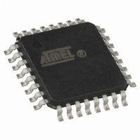
AT89LP428-20AU Atmel, AT89LP428-20AU Datasheet - Page 79

AT89LP428-20AU
Manufacturer Part Number
AT89LP428-20AU
Description
MCU 8051 4K FLASH SPI 32TQFP
Manufacturer
Atmel
Series
89LPr
Datasheet
1.AT89LP428-20AU.pdf
(149 pages)
Specifications of AT89LP428-20AU
Core Processor
8051
Core Size
8-Bit
Speed
20MHz
Connectivity
SPI, UART/USART
Peripherals
Brown-out Detect/Reset, POR, PWM, WDT
Number Of I /o
30
Program Memory Size
4KB (4K x 8)
Program Memory Type
FLASH
Eeprom Size
512 x 8
Ram Size
768 x 8
Voltage - Supply (vcc/vdd)
2.4 V ~ 5.5 V
Oscillator Type
Internal
Operating Temperature
-40°C ~ 85°C
Package / Case
32-TQFP, 32-VQFP
Processor Series
AT89x
Core
8051
3rd Party Development Tools
PK51, CA51, A51, ULINK2
Development Tools By Supplier
AT89ISP
Lead Free Status / RoHS Status
Lead free / RoHS Compliant
Data Converters
-
Lead Free Status / Rohs Status
Details
Available stocks
Company
Part Number
Manufacturer
Quantity
Price
Company:
Part Number:
AT89LP428-20AU
Manufacturer:
RFMD
Quantity:
1 240
16.2
16.2.1
3654A–MICRO–8/09
Baud Rates
Using Timer 1 to Generate Baud Rates
The baud rate in Mode 0 depends on the value of the SMOD1 bit in Special Function Register
PCON.7. If SMOD1 = 0 (the value on reset) and TB8 = 0, the baud rate is 1/4 of the oscillator
frequency. If SMOD1 = 1 and TB8 = 0, the baud rate is 1/2 of the oscillator frequency, as shown
in the following equation:
The baud rate in Mode 2 also depends on the value of the SMOD1 bit. If SMOD1 = 0, the baud
rate is 1/32 of the oscillator frequency. If SMOD1 = 1, the baud rate is 1/16 of the oscillator fre-
quency, as shown in the following equation:
Setting TB8 = 1 in Mode 0 enables Timer 1 as the baud rate generator. When Timer 1 is the
baud rate generator for Mode 0, the baud rates are determined by the Timer 1 overflow rate and
the value of SMOD1 according to the following equation:
The Timer 1 overflow rate normally determines the baud rates in Modes 1 and 3. When Timer 1
is the baud rate generator, the baud rates are determined by the Timer 1 overflow rate and the
value of SMOD1 according to the following equation:
The Timer 1 interrupt should be disabled in this application. The Timer itself can be configured
for either timer or counter operation in any of its 3 running modes. In the most typical applica-
tions, it is configured for timer operation in auto-reload mode (high nibble of TMOD = 0010B). In
this case, the baud rate is given by the following formula:
Mode 0 Baud Rate
Modes 1, 3
Baud Rate
Mode 0 Baud Rate
Mode 2 Baud Rate
Modes 1, 3
Baud Rate
TB8 = 1
TB8 = 0
=
2
------------------- -
=
SMOD1
32
2
------------------- -
SMOD1
=
32
=
=
2
------------------- -
×
SMOD1
2
------------------- -
2
------------------- -
Oscillator Frequency
------------------------------------------------------ -
SMOD1
SMOD1
4
32
×
4
[
(Timer 1 Overflow Rate)
256
×
×
×
(Timer 1 Overflow Rate)
–
Oscillator Frequency
Oscillator Frequency
(
TH1
)
]
×
AT89LP428/828
-------------------- -
TPS
1
+
1
79


