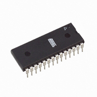
ATMEGA8L-8PU Atmel, ATMEGA8L-8PU Datasheet - Page 47

ATMEGA8L-8PU
Manufacturer Part Number
ATMEGA8L-8PU
Description
IC AVR MCU 8K 8MHZ 3V 28DIP
Manufacturer
Atmel
Series
AVR® ATmegar
Datasheets
1.ATMEGA8L-8MU.pdf
(25 pages)
2.ATMEGA8L-8MU.pdf
(302 pages)
3.ATMEGA8-16PU.pdf
(305 pages)
Specifications of ATMEGA8L-8PU
Core Processor
AVR
Core Size
8-Bit
Speed
8MHz
Connectivity
I²C, SPI, UART/USART
Peripherals
Brown-out Detect/Reset, POR, PWM, WDT
Number Of I /o
23
Program Memory Size
8KB (4K x 16)
Program Memory Type
FLASH
Eeprom Size
512 x 8
Ram Size
1K x 8
Voltage - Supply (vcc/vdd)
2.7 V ~ 5.5 V
Data Converters
A/D 6x10b
Oscillator Type
Internal
Operating Temperature
-40°C ~ 85°C
Package / Case
28-DIP (0.300", 7.62mm)
Cpu Family
ATmega
Device Core
AVR
Device Core Size
8b
Frequency (max)
8MHz
Interface Type
SPI/TWI/USART
Total Internal Ram Size
1KB
# I/os (max)
23
Number Of Timers - General Purpose
3
Operating Supply Voltage (typ)
3.3/5V
Operating Supply Voltage (max)
5.5V
Operating Supply Voltage (min)
2.7V
On-chip Adc
6-chx10-bit
Instruction Set Architecture
RISC
Operating Temp Range
-40C to 85C
Operating Temperature Classification
Industrial
Mounting
Through Hole
Pin Count
28
Package Type
PDIP
Processor Series
ATMEGA8x
Core
AVR8
Data Bus Width
8 bit
Data Ram Size
1 KB
Maximum Clock Frequency
8 MHz
Number Of Programmable I/os
23
Number Of Timers
3
Operating Supply Voltage
2.7 V to 5.5 V
Maximum Operating Temperature
+ 85 C
Mounting Style
Through Hole
3rd Party Development Tools
EWAVR, EWAVR-BL
Minimum Operating Temperature
- 40 C
Controller Family/series
AVR MEGA
No. Of I/o's
23
Eeprom Memory Size
512Byte
Ram Memory Size
1KB
Cpu Speed
8MHz
Rohs Compliant
Yes
For Use With
ATSTK600-TQFP32 - STK600 SOCKET/ADAPTER 32-TQFPATSTK600-DIP40 - STK600 SOCKET/ADAPTER 40-PDIP770-1007 - ISP 4PORT ATMEL AVR MCU SPI/JTAGATAVRISP2 - PROGRAMMER AVR IN SYSTEMATSTK500 - PROGRAMMER AVR STARTER KIT
Lead Free Status / RoHS Status
Lead free / RoHS Compliant
Available stocks
Company
Part Number
Manufacturer
Quantity
Price
Company:
Part Number:
ATMEGA8L-8PU
Manufacturer:
BROADCOM
Quantity:
101
Company:
Part Number:
ATMEGA8L-8PU
Manufacturer:
ATMEL
Quantity:
33 600
Part Number:
ATMEGA8L-8PU
Manufacturer:
ATMEL/爱特梅尔
Quantity:
20 000
Company:
Part Number:
ATMEGA8L-8PU-QS096
Manufacturer:
ATMEL
Quantity:
56
2486Z–AVR–02/11
Table 19. Reset and Interrupt Vectors Placement
Note:
The most typical and general program setup for the Reset and Interrupt Vector Addresses in
ATmega8 is:
BOOTRST
addressLabels Code
$000
$001
$002
$003
$004
$005
$006
$007
$008
$009
$00a
$00b
$00c
$00d
$00e
$00f
$010
$011
$012
;
$013
$014
$015
$016
$017
$018
...
1
1
0
0
1. The Boot Reset Address is shown in
(1)
means unprogrammed while “0” means programmed
RESET: ldi
IVSEL
0
1
0
1
rjmp
rjmp
rjmp
rjmp
rjmp
rjmp
rjmp
rjmp
rjmp
rjmp
rjmp
rjmp
rjmp
rjmp
rjmp
rjmp
rjmp
rjmp
rjmp
out
ldi
out
sei
<instr>
...
Reset Address
0x000
0x000
Boot Reset Address
Boot Reset Address
RESET
EXT_INT0
EXT_INT1
TIM2_COMP
TIM2_OVF
TIM1_CAPT
TIM1_COMPA
TIM1_COMPB
TIM1_OVF
TIM0_OVF
SPI_STC
USART_RXC
USART_UDRE
USART_TXC
ADC
EE_RDY
ANA_COMP
TWSI
SPM_RDY
SPH,r16
r16,low(RAMEND)
SPL,r16
...
xxx
r16,high(RAMEND); Main program start
Comments
; Reset Handler
; IRQ0 Handler
; IRQ1 Handler
; Timer2 Compare Handler
; Timer2 Overflow Handler
; Timer1 Capture Handler
; Timer1 CompareA Handler
; Timer1 CompareB Handler
; Timer1 Overflow Handler
; Timer0 Overflow Handler
; SPI Transfer Complete Handler
; USART RX Complete Handler
; UDR Empty Handler
; USART TX Complete Handler
; ADC Conversion Complete Handler
; EEPROM Ready Handler
; Analog Comparator Handler
; Two-wire Serial Interface Handler
; Store Program Memory Ready Handler
; Set Stack Pointer to top of RAM
; Enable interrupts
Table 82 on page
Interrupt Vectors Start Address
0x001
Boot Reset Address + 0x001
0x001
Boot Reset Address + 0x001
213. For the BOOTRST Fuse “1”
ATmega8(L)
47


