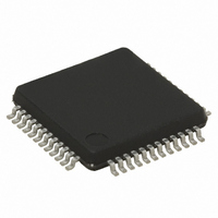
ST72F63BH6T1 STMicroelectronics, ST72F63BH6T1 Datasheet - Page 103

ST72F63BH6T1
Manufacturer Part Number
ST72F63BH6T1
Description
IC MCU 8BIT 32K FLASH 48-LQFP
Manufacturer
STMicroelectronics
Series
ST7r
Datasheet
1.ST72F63BD6U1TR.pdf
(186 pages)
Specifications of ST72F63BH6T1
Core Processor
ST7
Core Size
8-Bit
Speed
8MHz
Connectivity
I²C, SCI, USB
Peripherals
DMA, LVD, POR, PWM, WDT
Number Of I /o
27
Program Memory Size
32KB (32K x 8)
Program Memory Type
FLASH
Ram Size
1K x 8
Voltage - Supply (vcc/vdd)
4 V ~ 5.5 V
Data Converters
A/D 12x8b
Oscillator Type
External
Operating Temperature
0°C ~ 70°C
Package / Case
48-LQFP
Processor Series
ST72F6x
Core
ST7
Data Bus Width
8 bit
Data Ram Size
1 KB
Interface Type
I2C, SCI
Maximum Clock Frequency
8 MHz
Number Of Programmable I/os
27
Number Of Timers
1
Maximum Operating Temperature
+ 70 C
Mounting Style
SMD/SMT
Development Tools By Supplier
ST7MDTU3-EPB/US, ST72F63B-SK/RAIS, ST7MDTU3-EMU3, STX-RLINK
Minimum Operating Temperature
0 C
On-chip Adc
8 bit, 8 Channel / 8 bit, 12 Channel
For Use With
497-5521 - EVAL BOARD LOW SPEED USB
Lead Free Status / RoHS Status
Lead free / RoHS Compliant
Eeprom Size
-
Lead Free Status / Rohs Status
Details
Available stocks
Company
Part Number
Manufacturer
Quantity
Price
Company:
Part Number:
ST72F63BH6T1
Manufacturer:
TI
Quantity:
10
Company:
Part Number:
ST72F63BH6T1
Manufacturer:
STMicroelectronics
Quantity:
10 000
ST7263Bxx
Control register (CTLR)
Reset value: 0000 0110 (06h)
Device Address register (DADDR)
Reset value: 0000 0000 (00h)
7
0
7
0
[6:0] ADD[6:0] Device address, 7 bits.
[7:4] Reserved. Forced by hardware to 0.
0
ADD6
7 Reserved. Forced by hardware to 0.
3 RESUME Resume.
2 PDWN Power down.
1 FSUSP Force suspend mode.
0 FRES Force reset.
Software must write into this register the address sent by the host during
enumeration.
Note: This register is also reset when a USB reset is received from the USB bus or
This bit is set by software to wakeup the Host when the ST7 is in suspend mode.
0: Resume signal not forced
1: Resume signal forced on the USB bus.
Software should clear this bit after the appropriate delay.
This bit is set by software to turn off the 3.3 V on-chip voltage regulator that
supplies the external pull-up resistor and the transceiver.
0: Voltage regulator on
1: Voltage regulator off
Note: After turning on the voltage regulator, software should allow at least 3 µs for
This bit is set by software to enter Suspend mode. The ST7 should also be halted
allowing at least 600 ns before issuing the HALT instruction.
0: Suspend mode inactive
1: Suspend mode active
When the hardware detects USB activity, it resets this bit (it can also be reset by
software).
This bit is set by software to force a reset of the USB interface, just as if a RESET
sequence came from the USB.
0: Reset not forced
1: USB interface reset forced.
The USB is held in RESET state until software clears this bit, at which point a “USB-
RESET” interrupt will be generated if enabled.
0
forced through bit FRES in the CTLR register.
stabilization of the power supply before using the USB interface.
ADD5
0
Doc ID 7516 Rev 8
ADD4
RESUME
Read/write
Read.write
ADD3
PDWN
ADD2
FSUSP
On-chip peripherals
ADD1
FRES
ADD0
103/186
0
0


