C8051F521A-IM Silicon Laboratories Inc, C8051F521A-IM Datasheet - Page 138
C8051F521A-IM
Manufacturer Part Number
C8051F521A-IM
Description
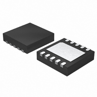
IC 8051 MCU 8K FLASH 10DFN
Manufacturer
Silicon Laboratories Inc
Series
C8051F52xr
Specifications of C8051F521A-IM
Program Memory Type
FLASH
Program Memory Size
8KB (8K x 8)
Package / Case
10-DFN
Core Processor
8051
Core Size
8-Bit
Speed
25MHz
Connectivity
SPI, UART/USART
Peripherals
Brown-out Detect/Reset, POR, PWM, Temp Sensor, WDT
Number Of I /o
6
Ram Size
256 x 8
Voltage - Supply (vcc/vdd)
1.8 V ~ 5.25 V
Data Converters
A/D 6x12b
Oscillator Type
Internal
Operating Temperature
-40°C ~ 125°C
Processor Series
C8051F5x
Core
8051
Data Bus Width
8 bit
Data Ram Size
256 B
Interface Type
SPI/UART
Maximum Clock Frequency
25 MHz
Number Of Programmable I/os
6
Number Of Timers
3
Maximum Operating Temperature
+ 125 C
Mounting Style
SMD/SMT
3rd Party Development Tools
PK51, CA51, A51, ULINK2
Development Tools By Supplier
C8051F500DK
Minimum Operating Temperature
- 40 C
On-chip Adc
6-ch x 12-bit
Lead Free Status / RoHS Status
Lead free / RoHS Compliant
For Use With
336-1488 - KIT DEV C8051F53XA, C8051F52XA770-1006 - ISP 4PORT FOR SILABS C8051F MCU336-1455 - ADAPTER PROGRAM TOOLSTICK F520
Eeprom Size
-
Lead Free Status / Rohs Status
Lead free / RoHS Compliant
Other names
336-1490-5


C8051F52x/F52xA/F53x/F53xA
14.2. External Oscillator Drive Circuit
The external oscillator circuit may drive an external crystal, ceramic resonator, capacitor, or RC network. A
CMOS clock may also provide a clock input. For a crystal or ceramic resonator configuration, the crys-
tal/resonator must be wired across the XTAL1 and XTAL2 pins as shown in Option 1 of Figure 14.1. A
10 Mresistor also must be wired across the XTAL1 and XTAL2 pins for the crystal/resonator configura-
tion. In RC, capacitor, or CMOS clock configuration, the clock source should be wired to the XTAL2 pin as
shown in Option 2, 3, or 4 of Figure 14.1. The type of external oscillator must be selected in the OSCXCN
register, and the frequency control bits (XFCN) must be selected appropriately (see SFR
Definition 14.4. OSCXCN: External Oscillator Control).
Important Note on External Oscillator Usage: Port pins must be configured when using the external
oscillator circuit. When the external oscillator drive circuit is enabled in crystal/resonator mode, Port pins
P0.7 and P1.0 ('F53x/'F53xA) or P0.2 and P0.3 ('F52x/'F52xA) are used as XTAL1 and XTAL2 respec-
tively. When the external oscillator drive circuit is enabled in capacitor, RC, or CMOS clock mode, Port pin
P1.0 ('F53x/'F53xA) or P0.3 ('F52x/'F52xA) is used as XTAL2. The Port I/O Crossbar should be configured
to skip the Port pins used by the oscillator circuit; see Section “13.1. Priority Crossbar Decoder” on
page 121 for Crossbar configuration. Additionally, when using the external oscillator circuit in crystal/reso-
nator, capacitor, or RC mode, the associated Port pins should be configured as analog inputs. In CMOS
clock mode, the associated pin should be configured as a digital input. See Section “13.2. Port I/O Initial-
ization” on page 125 for details on Port input mode selection.
14.2.1. Clocking Timers Directly Through the External Oscillator
The external oscillator source divided by eight is a clock option for the timers (Section “18. Timers” on
page 181) and the Programmable Counter Array (PCA) (Section “19. Programmable Counter Array
(PCA0)” on page 194). When the external oscillator is used to clock these peripherals, but is not used as
the system clock, the external oscillator frequency must be less than or equal to the system clock fre-
quency. In this configuration, the clock supplied to the peripheral (external oscillator / 8) is synchronized
with the system clock; the jitter associated with this synchronization is limited to ±0.5 system clock cycles.
14.2.2. External Crystal Example
If a crystal or ceramic resonator is used as an external oscillator source for the MCU, the circuit should be
configured as shown in Figure 14.1, Option 1. The External Oscillator Frequency Control value (XFCN)
should be chosen from the Crystal column of the table in SFR Definition 14.4. For example, a 12 MHz crys-
tal requires an XFCN setting of 111b.
When the crystal oscillator is first enabled, the oscillator amplitude detection circuit requires a settling time
to achieve proper bias. Introducing a delay of 1 ms between enabling the oscillator and checking the
XTLVLD bit will prevent a premature switch to the external oscillator as the system clock. Switching to the
external oscillator before the crystal oscillator has stabilized can result in unpredictable behavior. The rec-
ommended procedure is:
1. Configure XTAL1 and XTAL2 pins by writing 1 to the port latch.
2. Configure XTAL1 and XTAL2 as analog inputs.
3. Enable the external oscillator.
4. Wait at least 1 ms.
5. Poll for XTLVLD => 1.
6. Switch the system clock to the external oscillator.
Note: Tuning-fork crystals may require additional settling time before XTLVLD returns a valid result.
The capacitors shown in the external crystal configuration provide the load capacitance required by the
crystal for correct oscillation. These capacitors are "in series" as seen by the crystal and "in parallel" with
the stray capacitance of the XTAL1 and XTAL2 pins.
138
Rev. 1.3
Related parts for C8051F521A-IM
Image
Part Number
Description
Manufacturer
Datasheet
Request
R

Part Number:
Description:
SMD/C°/SINGLE-ENDED OUTPUT SILICON OSCILLATOR
Manufacturer:
Silicon Laboratories Inc
Part Number:
Description:
Manufacturer:
Silicon Laboratories Inc
Datasheet:
Part Number:
Description:
N/A N/A/SI4010 AES KEYFOB DEMO WITH LCD RX
Manufacturer:
Silicon Laboratories Inc
Datasheet:
Part Number:
Description:
N/A N/A/SI4010 SIMPLIFIED KEY FOB DEMO WITH LED RX
Manufacturer:
Silicon Laboratories Inc
Datasheet:
Part Number:
Description:
N/A/-40 TO 85 OC/EZLINK MODULE; F930/4432 HIGH BAND (REV E/B1)
Manufacturer:
Silicon Laboratories Inc
Part Number:
Description:
EZLink Module; F930/4432 Low Band (rev e/B1)
Manufacturer:
Silicon Laboratories Inc
Part Number:
Description:
I°/4460 10 DBM RADIO TEST CARD 434 MHZ
Manufacturer:
Silicon Laboratories Inc
Part Number:
Description:
I°/4461 14 DBM RADIO TEST CARD 868 MHZ
Manufacturer:
Silicon Laboratories Inc
Part Number:
Description:
I°/4463 20 DBM RFSWITCH RADIO TEST CARD 460 MHZ
Manufacturer:
Silicon Laboratories Inc
Part Number:
Description:
I°/4463 20 DBM RADIO TEST CARD 868 MHZ
Manufacturer:
Silicon Laboratories Inc
Part Number:
Description:
I°/4463 27 DBM RADIO TEST CARD 868 MHZ
Manufacturer:
Silicon Laboratories Inc
Part Number:
Description:
I°/4463 SKYWORKS 30 DBM RADIO TEST CARD 915 MHZ
Manufacturer:
Silicon Laboratories Inc
Part Number:
Description:
N/A N/A/-40 TO 85 OC/4463 RFMD 30 DBM RADIO TEST CARD 915 MHZ
Manufacturer:
Silicon Laboratories Inc
Part Number:
Description:
I°/4463 20 DBM RADIO TEST CARD 169 MHZ
Manufacturer:
Silicon Laboratories Inc