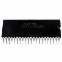
TMP86FH46ANG(Z) Toshiba, TMP86FH46ANG(Z) Datasheet - Page 115

TMP86FH46ANG(Z)
Manufacturer Part Number
TMP86FH46ANG(Z)
Description
IC MCU 8BIT FLASH 16KB 42-SDIP
Manufacturer
Toshiba
Series
TLCS-870/Cr
Datasheet
1.TMP86FH46ANGZ.pdf
(214 pages)
Specifications of TMP86FH46ANG(Z)
Core Processor
870/C
Core Size
8-Bit
Speed
16MHz
Connectivity
SIO, UART/USART
Peripherals
LED, PWM, WDT
Number Of I /o
33
Program Memory Size
16KB (16K x 8)
Program Memory Type
FLASH
Ram Size
512 x 8
Voltage - Supply (vcc/vdd)
2.7 V ~ 5.5 V
Data Converters
A/D 8x10b
Oscillator Type
Internal
Operating Temperature
-40°C ~ 85°C
Package / Case
42-SDIP (0.600", 15.24mm)
Processor Series
TLCS-870
Core
870/C
Data Bus Width
8 bit
Data Ram Size
512 B
Interface Type
SIO, UART
Maximum Clock Frequency
16 MHz
Number Of Programmable I/os
33
Number Of Timers
3
Maximum Operating Temperature
+ 85 C
Mounting Style
Through Hole
Development Tools By Supplier
BMSKTOPAS86FH47(AND), BM1040R0A, BMP86A100010A, BMP86A100010B, BMP86A200010B, BMP86A200020A, BMP86A300010A, BMP86A300020A, BMP86A300030A, SW89CN0-ZCC, SW00MN0-ZCC
Minimum Operating Temperature
- 40 C
On-chip Adc
10 bit, 8 Channel
For Use With
BM1401W0A-G - FLASH WRITER ON-BOARD PROGRAMTMP86C909XB - EMULATION CHIP FOR TMP86F SDIP
Lead Free Status / RoHS Status
Lead free / RoHS Compliant
Eeprom Size
-
Lead Free Status / Rohs Status
Details
Other names
TMP86FH46ANGZ
- Current page: 115 of 214
- Download datasheet (3Mb)
Example :After checking low-frequency clock oscillation stability with TC4 and 3, switching to the SLOW1 mode
9.3.9 Warm-Up Counter Mode
9.3.9.1
switched between the high-frequency and low-frequency. The timer counter 3 and 4 are cascadable to form a
16-bit TimerCouter. The warm-up counter mode has two types of mode; switching from the high-frequency to
low-frequency, and vice-versa.
Table 9-8 Setting Time of Low-Frequency Warm-Up Counter Mode (fs = 32.768 kHz)
In this mode, the warm-up period time is obtained to assure oscillation stability when the system clocking is
Note 1: In the warm-up counter mode, fix TCiCR<TFFi> to 0. If not fixed, the
Note 2: In the warm-up counter mode, only upper 8 bits of the timer register TTREG4 and 3 are used for match
Note 3: i = 3, 4
PINTTC4:
VINTTC4:
is obtained. Before starting the timer, set SYSCR2<XTEN> to 1 to oscillate the low-frequency clock.
When a match between the up-counter and the timer register (TTREG4, 3) value is detected after the timer
is started by setting TC4CR<TC4S> to 1, the counter is cleared by generating the INTTC4 interrupt
request. After stopping the timer in the INTTC4 interrupt service routine, set SYSCR2<SYSCK> to 1 to
switch the system clock from the high-frequency to low-frequency, and then clear of SYSCR2<XTEN> to
0 to stop the high-frequency clock.
(NORMAL1 → NORMAL2 → SLOW2 → SLOW1)
Low-Frequency Warm-up Counter Mode
In this mode, the warm-up period time from a stop of the low-frequency clock fs to oscillation stability
pulses.
detection and lower 8 bits are not used.
Maximum Time Setting
SET
LD
LD
LD
DI
SET
EI
SET
CLR
SET
CLR
RETI
DW
(TTREG4, 3 = 0100H)
:
:
7.81 ms
(SYSCR2).6
(TC3CR), 43H
(TC4CR), 05H
(TTREG3), 8000H
(EIRH). 1
(TC4CR).3
(TC4CR).3
(SYSCR2).5
(SYSCR2).7
PINTTC4
:
:
Page 101
: SYSCR2<XTEN>
: Sets TFF3=0, source clock fs, and 16-bit mode.
: Sets TFF4=0, and warm-up counter mode.
: Sets the warm-up time.
: IMF
: Enables the INTTC4.
: IMF
: Starts TC4 and 3.
: Stops TC4 and 3.
: SYSCR2<SYSCK>
: SYSCR2<XEN>
: INTTC4 vector table
(Switches the system clock to the low-frequency clock.)
(The warm-up time depends on the oscillator characteristic.)
←
←
0
1
←
←
Maximum Time Setting
(TTREG4, 3 = FF00H)
←
0 (Stops the high-frequency clock.)
1
1
PDOi
1.99 s
,
PWMi
and
PPGi
pins may output
TMP86FH46ANG
Related parts for TMP86FH46ANG(Z)
Image
Part Number
Description
Manufacturer
Datasheet
Request
R
Part Number:
Description:
Toshiba Semiconductor [TOSHIBA IGBT Module Silicon N Channel IGBT]
Manufacturer:
TOSHIBA Semiconductor CORPORATION
Datasheet:
Part Number:
Description:
TOSHIBA GTR MODULE SILICON NPN TRIPLE DIFFUSED TYPE
Manufacturer:
TOSHIBA Semiconductor CORPORATION
Datasheet:
Part Number:
Description:
TOSHIBA GTR Module Silicon N Channel IGBT
Manufacturer:
TOSHIBA Semiconductor CORPORATION
Datasheet:
Part Number:
Description:
TOSHIBA Intelligent Power Module Silicon N Channel IGBT
Manufacturer:
TOSHIBA Semiconductor CORPORATION
Datasheet:
Part Number:
Description:
TOSHIBA INTELLIGENT POWER MODULE SILICON N CHANNEL LGBT
Manufacturer:
TOSHIBA Semiconductor CORPORATION
Datasheet:
Part Number:
Description:
TOSHIBA IGBT Module Silicon N Channel IGBT
Manufacturer:
TOSHIBA Semiconductor CORPORATION
Datasheet:
Part Number:
Description:
TOSHIBA GTR MODULE SILICON N−CHANNEL IGBT
Manufacturer:
TOSHIBA Semiconductor CORPORATION
Datasheet:
Part Number:
Description:
TOSHIBA Intelligent Power Module Silicon N Channel IGBT
Manufacturer:
TOSHIBA Semiconductor CORPORATION
Datasheet:
Part Number:
Description:
TOSHIBA GTR Module Silicon N Channel IGBT
Manufacturer:
TOSHIBA Semiconductor CORPORATION
Datasheet:
Part Number:
Description:
TOSHIBA INTELLIGENT POWER MODULE
Manufacturer:
TOSHIBA Semiconductor CORPORATION
Datasheet:
Part Number:
Description:
TOSHIBA Intelligent Power Module Silicon N Channel IGBT
Manufacturer:
TOSHIBA Semiconductor CORPORATION
Datasheet:
Part Number:
Description:
TOSHIBA Intelligent Power Module Silicon N Channel IGBT
Manufacturer:
TOSHIBA Semiconductor CORPORATION
Datasheet:
Part Number:
Description:
TOSHIBA IGBT Module Silicon N Channel IGBT
Manufacturer:
TOSHIBA Semiconductor CORPORATION
Datasheet:
Part Number:
Description:
TOSHIBA Intelligent Power Module Silicon N Channel IGBT
Manufacturer:
TOSHIBA Semiconductor CORPORATION
Datasheet:
Part Number:
Description:
Toshiba Semiconductor [SILICON N CHANNEL 1GBT]
Manufacturer:
TOSHIBA Semiconductor CORPORATION
Datasheet:


