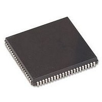
HD64F3337YCP16V Renesas Electronics America, HD64F3337YCP16V Datasheet - Page 573

HD64F3337YCP16V
Manufacturer Part Number
HD64F3337YCP16V
Description
MCU 3/5V 60K PB-FREE 84-PLCC
Manufacturer
Renesas Electronics America
Series
H8® H8/300r
Specifications of HD64F3337YCP16V
Core Size
8-Bit
Program Memory Size
60KB (60K x 8)
Oscillator Type
Internal
Core Processor
H8/300
Speed
16MHz
Connectivity
Host Interface, I²C, SCI
Peripherals
POR, PWM, WDT
Number Of I /o
74
Program Memory Type
FLASH
Ram Size
2K x 8
Voltage - Supply (vcc/vdd)
4.5 V ~ 5.5 V
Data Converters
A/D 8x10b; D/A 2x8b
Operating Temperature
-20°C ~ 75°C
Package / Case
84-PLCC
No. Of I/o's
74
Ram Memory Size
1KB
Cpu Speed
16MHz
No. Of Timers
6
No. Of Pwm Channels
2
Digital Ic Case Style
PLCC
Controller Family/series
H8/300
Rohs Compliant
Yes
Lead Free Status / RoHS Status
Lead free / RoHS Compliant
Eeprom Size
-
Lead Free Status / RoHS Status
Lead free / RoHS Compliant, Lead free / RoHS Compliant
Available stocks
Company
Part Number
Manufacturer
Quantity
Price
Company:
Part Number:
HD64F3337YCP16V
Manufacturer:
COILMASTER
Quantity:
30 000
Company:
Part Number:
HD64F3337YCP16V
Manufacturer:
Renesas Electronics America
Quantity:
10 000
- Current page: 573 of 747
- Download datasheet (4Mb)
22.3
22.3.1
To enter software standby mode, set the standby bit (SSBY) in the system control register
(SYSCR) to 1, then execute the SLEEP instruction.
In software standby mode, the system clock stops and chip functions halt, including both CPU
functions and the functions of the on-chip supporting modules. Power consumption is reduced to
an extremely low level. The on-chip supporting modules and their registers are reset to their initial
states, but as long as a minimum necessary voltage supply is maintained, the contents of the CPU
registers and on-chip RAM remain unchanged. I/O ports retain their states.
22.3.2
The chip can be brought out of software standby mode by an RES input, STBY input, or external
interrupt input at the NMI pin, IRQ
Exit by Interrupt: When an NMI, IRQ
clock oscillator begins operating. After the waiting time set in bits STS2 to STS0 of SYSCR, a
stable clock is supplied to the entire chip, software standby mode is released, and interrupt
exception-handling begins. IRQ
transition to software standby (clear IRQ3E, IRQ4E, IRQ5E, and IRQ7E to 0).
Exit by RES Pin: When the RES input goes low, the clock oscillator begins operating. When
RES is brought to the high level (after allowing time for the clock oscillator to settle), the CPU
starts reset exception handling. Be sure to hold RES low long enough for clock oscillation to
stabilize.
Exit by STBY Pin: When the STBY input goes low, the chip exits from software standby mode
to hardware standby mode.
Software Standby Mode
Transition to Software Standby Mode
Exit from Software Standby Mode
3
, IRQ
0
to IRQ
4
, IRQ
0
, IRQ
2
5
pins, or IRQ
, and IRQ
1
, IRQ
2
, or IRQ
7
interrupts should be disabled before the
6
pin (including KEYIN
6
interrupt request signal is input, the
0
to KEYIN
7
).
543
Related parts for HD64F3337YCP16V
Image
Part Number
Description
Manufacturer
Datasheet
Request
R

Part Number:
Description:
KIT STARTER FOR M16C/29
Manufacturer:
Renesas Electronics America
Datasheet:

Part Number:
Description:
KIT STARTER FOR R8C/2D
Manufacturer:
Renesas Electronics America
Datasheet:

Part Number:
Description:
R0K33062P STARTER KIT
Manufacturer:
Renesas Electronics America
Datasheet:

Part Number:
Description:
KIT STARTER FOR R8C/23 E8A
Manufacturer:
Renesas Electronics America
Datasheet:

Part Number:
Description:
KIT STARTER FOR R8C/25
Manufacturer:
Renesas Electronics America
Datasheet:

Part Number:
Description:
KIT STARTER H8S2456 SHARPE DSPLY
Manufacturer:
Renesas Electronics America
Datasheet:

Part Number:
Description:
KIT STARTER FOR R8C38C
Manufacturer:
Renesas Electronics America
Datasheet:

Part Number:
Description:
KIT STARTER FOR R8C35C
Manufacturer:
Renesas Electronics America
Datasheet:

Part Number:
Description:
KIT STARTER FOR R8CL3AC+LCD APPS
Manufacturer:
Renesas Electronics America
Datasheet:

Part Number:
Description:
KIT STARTER FOR RX610
Manufacturer:
Renesas Electronics America
Datasheet:

Part Number:
Description:
KIT STARTER FOR R32C/118
Manufacturer:
Renesas Electronics America
Datasheet:

Part Number:
Description:
KIT DEV RSK-R8C/26-29
Manufacturer:
Renesas Electronics America
Datasheet:

Part Number:
Description:
KIT STARTER FOR SH7124
Manufacturer:
Renesas Electronics America
Datasheet:

Part Number:
Description:
KIT STARTER FOR H8SX/1622
Manufacturer:
Renesas Electronics America
Datasheet:

Part Number:
Description:
KIT DEV FOR SH7203
Manufacturer:
Renesas Electronics America
Datasheet:


