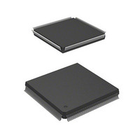
HD6417750RF240DV Renesas Electronics America, HD6417750RF240DV Datasheet - Page 953

HD6417750RF240DV
Manufacturer Part Number
HD6417750RF240DV
Description
MPU 3V 16K I-TEMP,PB-FREE 208-QF
Manufacturer
Renesas Electronics America
Series
SuperH® SH7750r
Datasheet
1.D6417750RBP240DV.pdf
(1164 pages)
Specifications of HD6417750RF240DV
Core Processor
SH-4
Core Size
32-Bit
Speed
240MHz
Connectivity
EBI/EMI, FIFO, SCI, SmartCard
Peripherals
DMA, POR, WDT
Number Of I /o
28
Program Memory Type
ROMless
Ram Size
48K x 8
Voltage - Supply (vcc/vdd)
1.4 V ~ 1.6 V
Oscillator Type
External
Operating Temperature
-40°C ~ 85°C
Package / Case
208-QFP
Lead Free Status / RoHS Status
Lead free / RoHS Compliant
Eeprom Size
-
Program Memory Size
-
Data Converters
-
Available stocks
Company
Part Number
Manufacturer
Quantity
Price
Company:
Part Number:
HD6417750RF240DV
Manufacturer:
HITACHI
Quantity:
7 287
- Current page: 953 of 1164
- Download datasheet (7Mb)
4. When an instruction access cycle is set for channel B, break data register B (BDRB) is ignored
20.3.5
1. In the case of an operand access cycle break, the bits included in address bus comparison vary
2. When data value is included in break conditions in channel B
3. When the DBEB bit in the break control register (BRCR) is set to 1, a break is not generated
in judging whether there is an instruction access match. Therefore, a break condition specified
by the DBEB bit in BRCR is not executed.
as shown below according to the data size specification in the break bus cycle register
(BBRA/BBRB).
When a data value is included in the break conditions, set the DBEB bit in the break control
register (BRCR) to 1. In this case, break data register B (BDRB) and break data mask register
B (BDMRB) settings are necessary in addition to the address condition. A user break interrupt
is generated when all three conditions—address, ASID, and data—are matched. When a
quadword access occurs, the 64-bit access data is divided into an upper 32 bits and lower 32
bits, and interpreted as two 32-bit data units. A break is generated if either of the 32-bit data
units satisfies the data match condition.
Set the IDB1–0 bits in break bus cycle register B (BBRB) to 10 or 11. When byte data is
specified, the same data should be set in the two bytes comprising bits 15–8 and bits 7–0 in
break data register B (BDRB) and break data mask register B (BDMRB). When word or byte
is set, bits 31–16 of BDRB and BDMRB are ignored.
by an operand access with no access data (an operand access in a PREF, OCBP, OCBWB, or
OCBI instruction).
Data Size
Quadword (100)
Longword (011)
Word (010)
Byte (001)
Not included in condition (000)
Operand Access Cycle Break
Address Bits Compared
Address bits A31–A3
Address bits A31–A2
Address bits A31–A1
Address bits A31–A0
In longword access, address bits A31–A2
In word access, address bits A31–A1
In byte access, address bits A31–A0
In quadword access, address bits A31–A3
Rev.7.00 Oct. 10, 2008 Page 867 of 1074
Section 20 User Break Controller (UBC)
REJ09B0366-0700
Related parts for HD6417750RF240DV
Image
Part Number
Description
Manufacturer
Datasheet
Request
R

Part Number:
Description:
KIT STARTER FOR M16C/29
Manufacturer:
Renesas Electronics America
Datasheet:

Part Number:
Description:
KIT STARTER FOR R8C/2D
Manufacturer:
Renesas Electronics America
Datasheet:

Part Number:
Description:
R0K33062P STARTER KIT
Manufacturer:
Renesas Electronics America
Datasheet:

Part Number:
Description:
KIT STARTER FOR R8C/23 E8A
Manufacturer:
Renesas Electronics America
Datasheet:

Part Number:
Description:
KIT STARTER FOR R8C/25
Manufacturer:
Renesas Electronics America
Datasheet:

Part Number:
Description:
KIT STARTER H8S2456 SHARPE DSPLY
Manufacturer:
Renesas Electronics America
Datasheet:

Part Number:
Description:
KIT STARTER FOR R8C38C
Manufacturer:
Renesas Electronics America
Datasheet:

Part Number:
Description:
KIT STARTER FOR R8C35C
Manufacturer:
Renesas Electronics America
Datasheet:

Part Number:
Description:
KIT STARTER FOR R8CL3AC+LCD APPS
Manufacturer:
Renesas Electronics America
Datasheet:

Part Number:
Description:
KIT STARTER FOR RX610
Manufacturer:
Renesas Electronics America
Datasheet:

Part Number:
Description:
KIT STARTER FOR R32C/118
Manufacturer:
Renesas Electronics America
Datasheet:

Part Number:
Description:
KIT DEV RSK-R8C/26-29
Manufacturer:
Renesas Electronics America
Datasheet:

Part Number:
Description:
KIT STARTER FOR SH7124
Manufacturer:
Renesas Electronics America
Datasheet:

Part Number:
Description:
KIT STARTER FOR H8SX/1622
Manufacturer:
Renesas Electronics America
Datasheet:

Part Number:
Description:
KIT DEV FOR SH7203
Manufacturer:
Renesas Electronics America
Datasheet:


