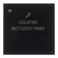
MCF5282CVM80 Freescale Semiconductor, MCF5282CVM80 Datasheet - Page 557

MCF5282CVM80
Manufacturer Part Number
MCF5282CVM80
Description
IC MPU 512K 80MHZ 256-MAPBGA
Manufacturer
Freescale Semiconductor
Series
MCF528xr
Datasheet
1.MCF5216CVM66J.pdf
(766 pages)
Specifications of MCF5282CVM80
Core Processor
Coldfire V2
Core Size
32-Bit
Speed
80MHz
Connectivity
CAN, EBI/EMI, Ethernet, I²C, SPI, UART/USART
Peripherals
DMA, LVD, POR, PWM, WDT
Number Of I /o
150
Program Memory Size
512KB (512K x 8)
Program Memory Type
FLASH
Ram Size
64K x 8
Voltage - Supply (vcc/vdd)
2.7 V ~ 3.6 V
Data Converters
A/D 8x10b
Oscillator Type
External
Operating Temperature
-40°C ~ 85°C
Package / Case
256-MAPBGA
Controller Family/series
ColdFire
Ram Memory Size
64KB
Embedded Interface Type
CAN, I2C, SPI, UART
No. Of Pwm Channels
8
Digital Ic Case Style
MAPBGA
Rohs Compliant
Yes
Lead Free Status / RoHS Status
Lead free / RoHS Compliant
Eeprom Size
-
Available stocks
Company
Part Number
Manufacturer
Quantity
Price
Company:
Part Number:
MCF5282CVM80
Manufacturer:
FREESCALE
Quantity:
1 831
Company:
Part Number:
MCF5282CVM80
Manufacturer:
Freescale Semiconductor
Quantity:
10 000
Company:
Part Number:
MCF5282CVM80J
Manufacturer:
Freescale Semiconductor
Quantity:
10 000
- Current page: 557 of 766
- Download datasheet (9Mb)
A queue is in the active state when a valid queue operating mode is selected, when the selected trigger
event has occurred, or when the QADC is performing a conversion specified by a CCW from that queue.
Only one queue can be active at a time.
One or both queues can be in the paused state. A queue is paused when the previous CCW executed from
that queue had the pause bit set. The QADC does not execute any CCWs from the paused queue until a
trigger event occurs. Consequently, the QADC can service queue 2 while queue 1 is paused.
Only queue 2 can be in the suspended state. When a trigger event occurs on queue 1 while queue 2 is
executing, the current queue 2 conversion is aborted and the queue 2 status is reported as suspended. Queue
2 transitions back to the active state when queue 1 becomes idle or paused.
A trigger pending state is required because both queues cannot be active at the same time. The status of
queue 2 is changed to trigger pending when a trigger event occurs for queue 2 while queue 1 is active. In
the opposite case, when a trigger event occurs for queue 1 while queue 2 is active, queue 2 is aborted and
the status is reported as queue 1 active, queue 2 suspended. So due to the priority scheme, only queue 2
can be in the trigger pending state.
Two transition cases cause the queue 2 status to be trigger pending before queue 2 is shown to be in the
active state. When queue 1 is active and there is a trigger pending on queue 2, after queue 1 completes or
pauses, queue 2 continues to be in the trigger pending state for a few clock cycles. The fleeting status
conditions are:
Figure 28-12
queue 1 active to queue 2 active.
When a queue enters the paused state, CWP points to the CCW with the pause bit set. While in pause, the
CWP value is maintained until a trigger event occurs on either queue. Usually, the CWP is updated a few
clock cycles before the queue status field shows that the queue has become active. For example, a read of
CWP may point to a CCW in queue 2, while the queue status field shows queue 1 paused and queue 2
trigger pending.
When the QADC finishes a queue scan, the CWP points to the CCW where the end-of-queue condition
was detected. Therefore, when the end-of-queue condition is a CCW with the EOQ code (channel 63), the
CWP points to the CCW containing the EOQ.
When the last CCW in a queue is the last CCW table location (CCW63), and it does not contain the EOQ
code, the end-of-queue is detected when the following CCW is read, so the CWP points to word CCW0.
Finally, when queue 1 operation is terminated after a CCW is read that is pointed to by BQ2, the CWP
points to the same CCW as BQ2.
Freescale Semiconductor
•
•
Queue 1 idle with queue 2 trigger pending
Queue 1 paused with queue 2 trigger pending
Reset
R/W:
Field
displays the status conditions of the QS field as the QADC goes through the transition from
CF1
15
MCF5282 and MCF5216 ColdFire Microcontroller User’s Manual, Rev. 3
PF1
14
CF2
13
R/W
PF2
12
0000_0000
TOR1
11
TOR2
Queued Analog-to-Digital Converter (QADC)
10
QS9
9
R
QS8
8
28-19
Related parts for MCF5282CVM80
Image
Part Number
Description
Manufacturer
Datasheet
Request
R
Part Number:
Description:
Mcf5282 And Mcf5216 Coldfire Microcontroller Userís Manual
Manufacturer:
Freescale Semiconductor, Inc
Datasheet:
Part Number:
Description:
Manufacturer:
Freescale Semiconductor, Inc
Datasheet:
Part Number:
Description:
Manufacturer:
Freescale Semiconductor, Inc
Datasheet:
Part Number:
Description:
Manufacturer:
Freescale Semiconductor, Inc
Datasheet:
Part Number:
Description:
Manufacturer:
Freescale Semiconductor, Inc
Datasheet:
Part Number:
Description:
Manufacturer:
Freescale Semiconductor, Inc
Datasheet:
Part Number:
Description:
Manufacturer:
Freescale Semiconductor, Inc
Datasheet:
Part Number:
Description:
Manufacturer:
Freescale Semiconductor, Inc
Datasheet:
Part Number:
Description:
Manufacturer:
Freescale Semiconductor, Inc
Datasheet:
Part Number:
Description:
Manufacturer:
Freescale Semiconductor, Inc
Datasheet:
Part Number:
Description:
Manufacturer:
Freescale Semiconductor, Inc
Datasheet:
Part Number:
Description:
Manufacturer:
Freescale Semiconductor, Inc
Datasheet:
Part Number:
Description:
Manufacturer:
Freescale Semiconductor, Inc
Datasheet:
Part Number:
Description:
Manufacturer:
Freescale Semiconductor, Inc
Datasheet:
Part Number:
Description:
Manufacturer:
Freescale Semiconductor, Inc
Datasheet:


