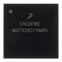
MCF5282CVM80 Freescale Semiconductor, MCF5282CVM80 Datasheet - Page 590

MCF5282CVM80
Manufacturer Part Number
MCF5282CVM80
Description
IC MPU 512K 80MHZ 256-MAPBGA
Manufacturer
Freescale Semiconductor
Series
MCF528xr
Datasheet
1.MCF5216CVM66J.pdf
(766 pages)
Specifications of MCF5282CVM80
Core Processor
Coldfire V2
Core Size
32-Bit
Speed
80MHz
Connectivity
CAN, EBI/EMI, Ethernet, I²C, SPI, UART/USART
Peripherals
DMA, LVD, POR, PWM, WDT
Number Of I /o
150
Program Memory Size
512KB (512K x 8)
Program Memory Type
FLASH
Ram Size
64K x 8
Voltage - Supply (vcc/vdd)
2.7 V ~ 3.6 V
Data Converters
A/D 8x10b
Oscillator Type
External
Operating Temperature
-40°C ~ 85°C
Package / Case
256-MAPBGA
Controller Family/series
ColdFire
Ram Memory Size
64KB
Embedded Interface Type
CAN, I2C, SPI, UART
No. Of Pwm Channels
8
Digital Ic Case Style
MAPBGA
Rohs Compliant
Yes
Lead Free Status / RoHS Status
Lead free / RoHS Compliant
Eeprom Size
-
Available stocks
Company
Part Number
Manufacturer
Quantity
Price
Company:
Part Number:
MCF5282CVM80
Manufacturer:
FREESCALE
Quantity:
1 831
Company:
Part Number:
MCF5282CVM80
Manufacturer:
Freescale Semiconductor
Quantity:
10 000
Company:
Part Number:
MCF5282CVM80J
Manufacturer:
Freescale Semiconductor
Quantity:
10 000
- Current page: 590 of 766
- Download datasheet (9Mb)
Queued Analog-to-Digital Converter (QADC)
trigger events. Because both queues may be triggered by the periodic/interval timer, see
“Periodic/Interval Timer
28.8.8
Figure 28-42
converter state machine which controls the timing of the conversion. The QCLK is also the input to a
17-stage binary divider which implements the periodic/interval timer. To retain the specified analog
conversion accuracy, the QCLK frequency (f
“Electrical
Before using the QADC, the prescaler must be initialized with values that put the QCLK within the
specified range. Though most applications initialize the prescaler once and do not change it, write
operations to the prescaler fields are permitted.
To accommodate the wide range of the system clock frequency, QCLK is generated by a programmable
prescaler which divides the system clock. To allow the A/D conversion time to be maximized across the
spectrum of system clock frequencies, the QADC prescaler permits the QCLK frequency to be software
selectable. The frequency of QCLK is set with the QPR field in QACR0.
28.8.9
The QADC periodic/interval timer can be used to generate trigger events at a programmable interval,
initiating execution of queue 1 and/or queue 2. The periodic/interval timer stays reset under these
conditions:
28-52
Queue 1 and Queue 2 Timer
Mode Rate Selection
QADC Clock (QCLK) Generation
Characteristics”.
Periodic/Interval Timer
System Clock
Input Sample Time
is a block diagram of the QCLK subsystem. The QCLK provides the timing for the A/D
A change in the prescaler value while a conversion is in progress is likely to
corrupt the result. Therefore, any prescaler write operation should be done
only when both queues are in the disabled modes.
Divide
from CCW
by 2
MCF5282 and MCF5216 ColdFire Microcontroller User’s Manual, Rev. 3
for a summary of periodic/interval timer reset conditions.
2
Figure 28-42. QADC Clock Subsystem Functions
8
2
7
Prescaler
QPR[6:0]
2
8
Periodic Timer/Interval Timer
2
9
2
10
QCLK
ATD Converter
Binary Counter
State Machine
2
CAUTION
11
Select
2
) must be within the tolerance specified in
12
2
13
2
14
2
15
2
16
2
17
2
Periodic/Interval Trigger
SAR Control
Event for Q1 and Q2
SAR
Freescale Semiconductor
10
Section 28.8.9,
Chapter 33,
Related parts for MCF5282CVM80
Image
Part Number
Description
Manufacturer
Datasheet
Request
R
Part Number:
Description:
Mcf5282 And Mcf5216 Coldfire Microcontroller Userís Manual
Manufacturer:
Freescale Semiconductor, Inc
Datasheet:
Part Number:
Description:
Manufacturer:
Freescale Semiconductor, Inc
Datasheet:
Part Number:
Description:
Manufacturer:
Freescale Semiconductor, Inc
Datasheet:
Part Number:
Description:
Manufacturer:
Freescale Semiconductor, Inc
Datasheet:
Part Number:
Description:
Manufacturer:
Freescale Semiconductor, Inc
Datasheet:
Part Number:
Description:
Manufacturer:
Freescale Semiconductor, Inc
Datasheet:
Part Number:
Description:
Manufacturer:
Freescale Semiconductor, Inc
Datasheet:
Part Number:
Description:
Manufacturer:
Freescale Semiconductor, Inc
Datasheet:
Part Number:
Description:
Manufacturer:
Freescale Semiconductor, Inc
Datasheet:
Part Number:
Description:
Manufacturer:
Freescale Semiconductor, Inc
Datasheet:
Part Number:
Description:
Manufacturer:
Freescale Semiconductor, Inc
Datasheet:
Part Number:
Description:
Manufacturer:
Freescale Semiconductor, Inc
Datasheet:
Part Number:
Description:
Manufacturer:
Freescale Semiconductor, Inc
Datasheet:
Part Number:
Description:
Manufacturer:
Freescale Semiconductor, Inc
Datasheet:
Part Number:
Description:
Manufacturer:
Freescale Semiconductor, Inc
Datasheet:


