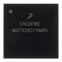
MCF5282CVM80 Freescale Semiconductor, MCF5282CVM80 Datasheet - Page 562

MCF5282CVM80
Manufacturer Part Number
MCF5282CVM80
Description
IC MPU 512K 80MHZ 256-MAPBGA
Manufacturer
Freescale Semiconductor
Series
MCF528xr
Datasheet
1.MCF5216CVM66J.pdf
(766 pages)
Specifications of MCF5282CVM80
Core Processor
Coldfire V2
Core Size
32-Bit
Speed
80MHz
Connectivity
CAN, EBI/EMI, Ethernet, I²C, SPI, UART/USART
Peripherals
DMA, LVD, POR, PWM, WDT
Number Of I /o
150
Program Memory Size
512KB (512K x 8)
Program Memory Type
FLASH
Ram Size
64K x 8
Voltage - Supply (vcc/vdd)
2.7 V ~ 3.6 V
Data Converters
A/D 8x10b
Oscillator Type
External
Operating Temperature
-40°C ~ 85°C
Package / Case
256-MAPBGA
Controller Family/series
ColdFire
Ram Memory Size
64KB
Embedded Interface Type
CAN, I2C, SPI, UART
No. Of Pwm Channels
8
Digital Ic Case Style
MAPBGA
Rohs Compliant
Yes
Lead Free Status / RoHS Status
Lead free / RoHS Compliant
Eeprom Size
-
Available stocks
Company
Part Number
Manufacturer
Quantity
Price
Company:
Part Number:
MCF5282CVM80
Manufacturer:
FREESCALE
Quantity:
1 831
Company:
Part Number:
MCF5282CVM80
Manufacturer:
Freescale Semiconductor
Quantity:
10 000
Company:
Part Number:
MCF5282CVM80J
Manufacturer:
Freescale Semiconductor
Quantity:
10 000
- Current page: 562 of 766
- Download datasheet (9Mb)
Queued Analog-to-Digital Converter (QADC)
28.6.7
The CCW table is 64 half-word (128 byte) long RAM with 10 bits of each entry implemented. The CCW
table is written by the user and is not modified by the QADC. Each CCW requests the conversion of one
analog channel to a digital result. The CCW specifies the analog channel number, the input sample time,
and whether the queue is to pause after the current CCW. The bits in this register are read anytime (except
during stop mode), write anytime (except during stop mode).
28-24
15–14
Bit(s)
13–8
Address
7–6
5–0
Reset
Reset
R/W:
R/W:
Field
Field
Conversion Command Word Table (CCW)
CWPQ1
CWPQ
15
Name
7
—
—
—
MCF5282 and MCF5216 ColdFire Microcontroller User’s Manual, Rev. 3
Figure 28-13. QADC Status Register 1 (QASR1)
6
Reserved, should be cleared.
Queue 1 command word pointer. Points to the last queue 1 CCW executed. This is a
read-only field with a valid range of 0 to 63; writes have no effect. CWPQ1 always
points to the last executed CCW in queue 1, regardless of which queue is active.
In contrast to CWP, CPWQ1 is updated when a conversion result is written. When the
QADC finishes a conversion in queue 1, both the result register is written and CWPQ1
is updated.
When queue 1 operation is terminated after a CCW is read that is pointed to by BQ2,
CWP points to BQ2 while CWPQ1 points to the last queue 1 CCW.
During stop mode, CWPQ1 is reset to 63, because the control registers and the
analog logic are reset. When debug mode is entered, CWPQ1 is not changed; it points
to the last executed CCW in queue 1.
Reserved, should be cleared.
Queue 2 command word pointer. Points to the last queue 2 CCW executed. This is a
read-only field with a valid range of 0 to 63; writes have no effect. CWPQ2 always
points to the last executed CCW in queue 2, regardless which queue is active.
In contrast to CWP, CPWQ2 is updated when a conversion result is written. When the
QADC finishes a conversion in queue 2, both the result register is written and CWPQ2
is updated.
During stop mode, CWPQ2 is reset to 63 because the control registers and the analog
logic are reset. When debug mode is entered, CWPQ2 is not changed; it points to the
last executed CCW in queue 2.
Table 28-13. QASR1 Field Descriptions
CWPQ25
5
IPSBAR + 0x19_0012, 0x19_0013
0000_00
—
R
CWPQ24
4
0011_1111
R
CWPQ23
Description
3
CWPQ22
10
2
CWPQ21
P
9
1
Unaffected
Freescale Semiconductor
R/W
CWPQ20
BYP
8
0
Related parts for MCF5282CVM80
Image
Part Number
Description
Manufacturer
Datasheet
Request
R
Part Number:
Description:
Mcf5282 And Mcf5216 Coldfire Microcontroller Userís Manual
Manufacturer:
Freescale Semiconductor, Inc
Datasheet:
Part Number:
Description:
Manufacturer:
Freescale Semiconductor, Inc
Datasheet:
Part Number:
Description:
Manufacturer:
Freescale Semiconductor, Inc
Datasheet:
Part Number:
Description:
Manufacturer:
Freescale Semiconductor, Inc
Datasheet:
Part Number:
Description:
Manufacturer:
Freescale Semiconductor, Inc
Datasheet:
Part Number:
Description:
Manufacturer:
Freescale Semiconductor, Inc
Datasheet:
Part Number:
Description:
Manufacturer:
Freescale Semiconductor, Inc
Datasheet:
Part Number:
Description:
Manufacturer:
Freescale Semiconductor, Inc
Datasheet:
Part Number:
Description:
Manufacturer:
Freescale Semiconductor, Inc
Datasheet:
Part Number:
Description:
Manufacturer:
Freescale Semiconductor, Inc
Datasheet:
Part Number:
Description:
Manufacturer:
Freescale Semiconductor, Inc
Datasheet:
Part Number:
Description:
Manufacturer:
Freescale Semiconductor, Inc
Datasheet:
Part Number:
Description:
Manufacturer:
Freescale Semiconductor, Inc
Datasheet:
Part Number:
Description:
Manufacturer:
Freescale Semiconductor, Inc
Datasheet:
Part Number:
Description:
Manufacturer:
Freescale Semiconductor, Inc
Datasheet:


