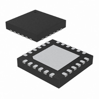
ATA5773-PXQW Atmel, ATA5773-PXQW Datasheet - Page 181

ATA5773-PXQW
Manufacturer Part Number
ATA5773-PXQW
Description
XMITTR UHF ASK/FSK 310MHZ 24VQFN
Manufacturer
Atmel
Datasheet
1.ATA5773-DK1.pdf
(219 pages)
Specifications of ATA5773-PXQW
Frequency
310MHz ~ 350MHz
Modulation Or Protocol
UHF
Power - Output
8dBm
Voltage - Supply
2 V ~ 4 V
Current - Transmitting
9.8mA
Data Interface
PCB, Surface Mount
Memory Size
4kB Flash, 256B EEPROM, 256B SRAM
Antenna Connector
PCB, Surface Mount
Operating Temperature
-40°C ~ 85°C
Package / Case
24-VQFN Exposed Pad, 24-HVQFN, 24-SQFN, 24-DHVQFN
Processor Series
ATA5x
Core
AVR8
Data Bus Width
8 bit
Program Memory Type
Flash
Program Memory Size
4 KB
Data Ram Size
256 B
Interface Type
SPI, USI
Maximum Clock Frequency
4 MHz
Number Of Programmable I/os
12
Number Of Timers
2
Maximum Operating Temperature
+ 85 C
Mounting Style
SMD/SMT
Minimum Operating Temperature
- 40 C
On-chip Adc
10 bit, 12 Channel
Lead Free Status / RoHS Status
Lead free / RoHS Compliant
Applications
-
Sensitivity
-
Data Rate - Maximum
-
Current - Receiving
-
Lead Free Status / Rohs Status
Details
Available stocks
Company
Part Number
Manufacturer
Quantity
Price
Company:
Part Number:
ATA5773-PXQW
Manufacturer:
ATMEL
Quantity:
3 500
Part Number:
ATA5773-PXQW
Manufacturer:
ATMEL/爱特梅尔
Quantity:
20 000
- Current page: 181 of 219
- Download datasheet (4Mb)
5. Application
9137E–RKE–12/10
Figure 5-1
sure of the power supply voltage, a capacitor value of C
and C
should be used to achieve a better tolerance value for C
ing the Z
Figure 5-1.
Together with the pins and the PCB board wires C
press the 1
best suppression is achieved when C
ANT2.
The loop antenna should not exceed a width of 1.5 mm, otherwise the Q-factor of the loop
antenna is too high.
The capacitor C
crystal.
2
are used to match the loop antenna to the power amplifier. Two capacitors in series
Load,opt
illustrates a principle application circuit using loop antenna. For the blocking mea-
st
harmonic. Therefore the position of C
The Principle Application Circuit Using a Loop Antenna for ASK Modulation
using standard valued capacitors.
4
should be selected that the XTO runs on the load resonance frequency of the
C4
S1
S1
S1
CLK
PXY
PXY
PXY
PXY
PXY
PXY
PXY
ATA5771/73/74
XTO
f/4
1
is placed as close as possible to the pins ANT1 and
Power
up /
down
VCO
PA
PLL
1
1
Atmel ATA5771/73/74
forms a series resonance loop that sup-
on the PCB is important. Generally the
VCC_RF
ANT2
GND_RF
2
ANT1
ENABLE
PA_ENABLE
VDD
GND
PXY
PXY
PXY
PXY
PXY
3
and allowing the possibility of realiz-
= 68 nF/X7R is recommended. C
VS
C1
C3
VS
C2
VS
Antenna
Loop
181
1
Related parts for ATA5773-PXQW
Image
Part Number
Description
Manufacturer
Datasheet
Request
R

Part Number:
Description:
BOARD XMITTER FOR ATA5773 315MHZ
Manufacturer:
Atmel
Datasheet:

Part Number:
Description:
Microcontroller With Uhf Ask/fsk Transmitter
Manufacturer:
ATMEL Corporation
Datasheet:

Part Number:
Description:
DEV KIT FOR AVR/AVR32
Manufacturer:
Atmel
Datasheet:

Part Number:
Description:
INTERVAL AND WIPE/WASH WIPER CONTROL IC WITH DELAY
Manufacturer:
ATMEL Corporation
Datasheet:

Part Number:
Description:
Low-Voltage Voice-Switched IC for Hands-Free Operation
Manufacturer:
ATMEL Corporation
Datasheet:

Part Number:
Description:
MONOLITHIC INTEGRATED FEATUREPHONE CIRCUIT
Manufacturer:
ATMEL Corporation
Datasheet:

Part Number:
Description:
AM-FM Receiver IC U4255BM-M
Manufacturer:
ATMEL Corporation
Datasheet:

Part Number:
Description:
Monolithic Integrated Feature Phone Circuit
Manufacturer:
ATMEL Corporation
Datasheet:

Part Number:
Description:
Multistandard Video-IF and Quasi Parallel Sound Processing
Manufacturer:
ATMEL Corporation
Datasheet:

Part Number:
Description:
High-performance EE PLD
Manufacturer:
ATMEL Corporation
Datasheet:

Part Number:
Description:
8-bit Flash Microcontroller
Manufacturer:
ATMEL Corporation
Datasheet:

Part Number:
Description:
2-Wire Serial EEPROM
Manufacturer:
ATMEL Corporation
Datasheet:


