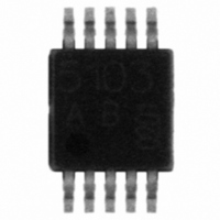
TDA5150 Infineon Technologies, TDA5150 Datasheet - Page 59

TDA5150
Manufacturer Part Number
TDA5150
Description
IC TX MULTI-CH/BAND 10-TSSOP
Manufacturer
Infineon Technologies
Type
Multiband Transmitterr
Datasheet
1.TDA5150.pdf
(106 pages)
Specifications of TDA5150
Package / Case
10-TSSOP
Frequency
300MHz ~ 320MHz, 425MHz ~ 450MHz, 863MHz ~ 928MHz
Applications
RKE, Security Systems
Modulation Or Protocol
ASK, FSK, GFSK
Data Rate - Maximum
50 kbps
Power - Output
10dBm
Current - Transmitting
16mA
Data Interface
PCB, Surface Mount
Antenna Connector
PCB, Surface Mount
Voltage - Supply
1.9 V ~ 3.6 V
Operating Temperature
-40°C ~ 85°C
Maximum Operating Temperature
+ 85 C
Mounting Style
SMD/SMT
Supply Current
16 mA
Supply Voltage (max)
3.6 V
Supply Voltage (min)
1.9 V
Lead Free Status / RoHS Status
Lead free / RoHS Compliant
Features
-
Memory Size
-
Lead Free Status / RoHS Status
Lead free / RoHS Compliant, Lead free / RoHS Compliant
Other names
SP000300415
TDA5150
TDA5150INTR
TDA5150
TDA5150INTR
Available stocks
Company
Part Number
Manufacturer
Quantity
Price
2.4.11
The procedure of RF Transmission starts by rising the EN line (pin 1) high. STANDBY
or SLEEP Mode are exited, and the crystal oscillator started. The crystal oscillator
requires maximum 1 ms to start up. During this time the TDA 5150 can be already
reconfigured, because the SPI block does not require the system clock. Before
transmission the Transmitter Status Register
previous errors, if any). Every transmission starts with the Transmit Command:
The Transmit Command byte is sent via SPI, and identified by the first two bits,
designated C0 and C1. These two bits are mandatory set to1.
The following 6 bits, designated bit A.. bit F, specify the transmission details.
•
Data Sheet
C1
A: Synchronous (1) or asynchronous (0) transmission, details are described later in
this chapter.
1
1
1
1
1
RF Data Transmission
C0
1
1
1
1
1
<E,F>
Bit
A
B
C
D
ModSetting
Frequency
Pwr. level/
Data sync
Function
Encoding
PA mode
selection
Transmit Command Configuration
59
0: off
1: on (at the same time Bit C - Encoding
must be set also to 1 -->int. Encoding)
0: PA off at the falling edge of EN
(synchronized with bit-rate if bit A is high)
1: SDIO/DATA is latched at the falling
edge of EN, PA stays on, TX data are kept
constant. After the time-out of 65536 / f
which is ~5 ms for a 13 MHz crystal, PA
and PLL are switched off.
0: off
1: on (selects SFR register for encoding
Bit A must be also set to1 -->Data sync)
0: selects PowerLevel/Modulation Setting1
1: selects Power Level/Modulation Setting2
0 (00): selects frequency channel A
1 (01): selects frequency channel B
2 (10): selects frequency channel C
3 (11): selects frequency channel D
(for description of frequency channels
A..D programming see
Chapter 2.4.11.3 Channel
(0x01)
TDA 5150 Functional Description
should be read (to clear bits set by
Value, description
Hopping)
V 1.0, July 2009
TDA 5150
sys


