NTHS0603N10N1502JE Vishay, NTHS0603N10N1502JE Datasheet - Page 31
NTHS0603N10N1502JE
Manufacturer Part Number
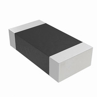
NTHS0603N10N1502JE
Description
THERMISTOR NTC 15K OHM 5% 0603
Manufacturer
Vishay
Series
NTHSr
Specifications of NTHS0603N10N1502JE
Resistance In Ohms @ 25°c
15K
Resistance Tolerance
±5%
B Value Tolerance
±3%
B25/75
3500K
Mounting Type
Surface Mount
Package / Case
0603 (1608 Metric)
Lead Free Status / RoHS Status
Lead free by exemption / RoHS Compliant
B0/50
-
B25/50
-
B25/85
-
B25/100
-
Operating Temperature
-
Power - Max
-
Lead Length
-
Lead Free Status / Rohs Status
Lead free / RoHS Compliant
Other names
541-1114-2
Available stocks
Company
Part Number
Manufacturer
Quantity
Price

Part Number:
NTHS0603N10N1502JE
Manufacturer:
VISHAY/威世
Quantity:
20 000


8.10
8.11
October 29, 2008 S29GL-N_01_12
8.11.1
Lock Register
Persistent Sector Protection
Dynamic Protection Bit (DYB)
The Lock Register consists of 3 bits (DQ2, DQ1, and DQ0). These DQ2, DQ1, DQ0 bits of the Lock Register
are programmable by the user. Users are not allowed to program both DQ2 and DQ1 bits of the Lock Register
to the 00 state. If the user tries to program DQ2 and DQ1 bits of the Lock Register to the 00 state, the device
aborts the Lock Register back to the default 11 state. The programming time of the Lock Register is same as
the typical word programming time (t
Register programming sequence execution, the DQ6 Toggle Bit I toggles until the programming of the Lock
Register has completed to indicate programming status. All Lock Register bits are readable to allow users to
verify Lock Register statuses.
The Customer Secured Silicon Sector Protection Bit is DQ0, Persistent Protection Mode Lock Bit is DQ1, and
Password Protection Mode Lock Bit is DQ2 are accessible by all users. Each of these bits are non-volatile.
DQ15-DQ3 are reserved and must be 1's when the user tries to program the DQ2, DQ1, and DQ0 bits of the
Lock Register. The user is not required to program DQ2, DQ1 and DQ0 bits of the Lock Register at the same
time. This allows users to lock the Secured Silicon Sector and then set the device either permanently into
Password Protection Mode or Persistent Protection Mode and then lock the Secured Silicon Sector at
separate instances and time frames.
The Persistent Sector Protection method replaces the old 12 V controlled protection method while at the
same time enhancing flexibility by providing three different sector protection states
To achieve these states, three types of “bits” are used:
A volatile protection bit is assigned for each sector. After power-up or hardware reset, the contents of all DYB
bits are in the “unprotected state”. Each DYB is individually modifiable through the DYB Set Command and
DYB Clear Command. The DYB bits and Persistent Protect Bits (PPB) Lock bit are defaulted to power up in
the cleared state or unprotected state - meaning the all PPB bits are changeable.
The Protection State for each sector is determined by the logical OR of the PPB and the DYB related to that
sector. For the sectors that have the PPB bits cleared, the DYB bits control whether or not the sector is
protected or unprotected. By issuing the DYB Set and DYB Clear command sequences, the DYB bits is
protected or unprotected, thus placing each sector in the protected or unprotected state. These are the so-
called Dynamic Locked or Unlocked states. They are called dynamic states because it is very easy to switch
back and forth between the protected and un-protected conditions. This allows software to easily protect
sectors against inadvertent changes yet does not prevent the easy removal of protection when changes are
needed.
The DYB bits maybe set or cleared as often as needed. The PPB bits allow for a more static, and difficult to
change, level of protection. The PPB bits retain their state across power cycles because they are Non-
Dynamically Locked
Persistently Locked
Unlocked
Secured Silicon Sector Protection allows the user to lock the Secured Silicon Sector area
Persistent Protection Mode Lock Bit allows the user to set the device permanently to operate in the
Persistent Protection Mode
Password Protection Mode Lock Bit allows the user to set the device permanently to operate in the
Password Protection Mode
Don’t Care
DQ15-3
D a t a
Password Protection Mode
S29GL-N MirrorBit
The sector is protected and can be changed by a simple command
A sector is protected and cannot be changed
The sector is unprotected and can be changed by a simple command
S h e e t
WHWH1
Lock Bit
DQ2
Table 8.10 Lock Register
) without utilizing the Write Buffer of the device. During a Lock
®
Flash Family
Persistent Protection Mode
Lock Bit
DQ1
Secured Silicon Sector
Protection Bit
DQ0
31
Related parts for NTHS0603N10N1502JE
Image
Part Number
Description
Manufacturer
Datasheet
Request
R

Part Number:
Description:
357-036-542-201 CARDEDGE 36POS DL .156 BLK LOPRO
Manufacturer:
Vishay
Datasheet:
Part Number:
Description:
357-036-542-201 CARDEDGE 36POS DL .156 BLK LOPRO
Manufacturer:
Vishay
Datasheet:
Part Number:
Description:
357-036-542-201 CARDEDGE 36POS DL .156 BLK LOPRO
Manufacturer:
Vishay
Datasheet:
Part Number:
Description:
357-036-542-201 CARDEDGE 36POS DL .156 BLK LOPRO
Manufacturer:
Vishay
Datasheet:
Part Number:
Description:
357-036-542-201 CARDEDGE 36POS DL .156 BLK LOPRO
Manufacturer:
Vishay
Datasheet:
Part Number:
Description:
357-036-542-201 CARDEDGE 36POS DL .156 BLK LOPRO
Manufacturer:
Vishay
Datasheet:
Part Number:
Description:
357-036-542-201 CARDEDGE 36POS DL .156 BLK LOPRO
Manufacturer:
Vishay
Datasheet:
Part Number:
Description:
357-036-542-201 CARDEDGE 36POS DL .156 BLK LOPRO
Manufacturer:
Vishay
Datasheet:
Part Number:
Description:
357-036-542-201 CARDEDGE 36POS DL .156 BLK LOPRO
Manufacturer:
Vishay
Datasheet:
Part Number:
Description:
357-036-542-201 CARDEDGE 36POS DL .156 BLK LOPRO
Manufacturer:
Vishay
Datasheet:
Part Number:
Description:
357-036-542-201 CARDEDGE 36POS DL .156 BLK LOPRO
Manufacturer:
Vishay
Datasheet:
Part Number:
Description:
357-036-542-201 CARDEDGE 36POS DL .156 BLK LOPRO
Manufacturer:
Vishay
Datasheet:
Part Number:
Description:
357-036-542-201 CARDEDGE 36POS DL .156 BLK LOPRO
Manufacturer:
Vishay
Datasheet:
Part Number:
Description:
357-036-542-201 CARDEDGE 36POS DL .156 BLK LOPRO
Manufacturer:
Vishay
Datasheet:
Part Number:
Description:
357-036-542-201 CARDEDGE 36POS DL .156 BLK LOPRO
Manufacturer:
Vishay
Datasheet: