NTHS0603N10N1502JE Vishay, NTHS0603N10N1502JE Datasheet - Page 61
NTHS0603N10N1502JE
Manufacturer Part Number
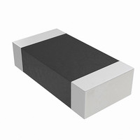
NTHS0603N10N1502JE
Description
THERMISTOR NTC 15K OHM 5% 0603
Manufacturer
Vishay
Series
NTHSr
Specifications of NTHS0603N10N1502JE
Resistance In Ohms @ 25°c
15K
Resistance Tolerance
±5%
B Value Tolerance
±3%
B25/75
3500K
Mounting Type
Surface Mount
Package / Case
0603 (1608 Metric)
Lead Free Status / RoHS Status
Lead free by exemption / RoHS Compliant
B0/50
-
B25/50
-
B25/85
-
B25/100
-
Operating Temperature
-
Power - Max
-
Lead Length
-
Lead Free Status / Rohs Status
Lead free / RoHS Compliant
Other names
541-1114-2
Available stocks
Company
Part Number
Manufacturer
Quantity
Price

Part Number:
NTHS0603N10N1502JE
Manufacturer:
VISHAY/威世
Quantity:
20 000


11. Absolute Maximum Ratings
12. Operating Ranges
October 29, 2008 S29GL-N_01_12
Notes
1. Minimum DC voltage on input or I/Os is –0.5 V. During voltage transitions, inputs or I/Os may overshoot V
2. Minimum DC input voltage on pins A9, ACC, and RESET# is –0.5 V. During voltage transitions, A9, ACC, and RESET# may overshoot
3. No more than one output may be shorted to ground at a time. Duration of the short circuit should not be greater than one second.
4. Stresses above those listed under Absolute Maximum Ratings may cause permanent damage to the device. This is a stress rating only;
Notes
1. Operating ranges define those limits between which the functionality of the device is guaranteed.
2. V
Storage Temperature, Plastic Packages
Ambient Temperature with Power Applied
Voltage with Respect to Ground
Output Short Circuit Current
Ambient Temperature (T
Supply Voltages
20 ns. See
to V
V
overshoot to +14.0 V for periods up to 20 ns.
functional operation of the device at these or any other conditions above those indicated in the operational sections of this data sheet is not
implied. Exposure of the device to absolute maximum rating conditions for extended periods may affect device reliability.
SS
IO
CC
input voltage always must be lower than V
to –2.0 V for periods of up to 20 ns. See
+ 2.0 V for periods up to 20 ns. See
Figure
11.1. Maximum DC voltage on input or I/Os is V
A
), Industrial (I) Devices
D a t a
+2.0 V
+0.5 V
Figure 11.1 Maximum Negative Overshoot Waveform
+0.8 V
–0.5 V
–2.0 V
Figure 11.2 Maximum Positive Overshoot Waveform
2.0 V
V
V
V
V
S29GL-N MirrorBit
CC
IO
CC
CC
for full voltage range
Parameter
S h e e t
Figure
Figure
Parameter
CC
input voltage.
11.2.
11.1. Maximum DC input voltage on pin A9, ACC, and RESET# is +12.5 V which may
V
A9, ACC and RESET#
All other pins
(Note 3)
20 ns
20 ns
CC
®
Flash Family
(Note 1)
CC
+ 0.5 V. During voltage transitions, input or I/O pins may overshoot
(Note 1)
20 ns
20 ns
(Note 2)
20 ns
20 ns
SS
–65°C to +150°C
–65°C to +125°C
–0.5 V to +4.0 V
–0.5 V to +12.5 V
–0.5 V to V
200 mA
to –2.0 V for periods of up to
+2.7 V to +3.6 V
–40°C to +85°C
+1.65 to +3.6 V
Range
Rating
CC
+0.5 V
61
Related parts for NTHS0603N10N1502JE
Image
Part Number
Description
Manufacturer
Datasheet
Request
R

Part Number:
Description:
357-036-542-201 CARDEDGE 36POS DL .156 BLK LOPRO
Manufacturer:
Vishay
Datasheet:
Part Number:
Description:
357-036-542-201 CARDEDGE 36POS DL .156 BLK LOPRO
Manufacturer:
Vishay
Datasheet:
Part Number:
Description:
357-036-542-201 CARDEDGE 36POS DL .156 BLK LOPRO
Manufacturer:
Vishay
Datasheet:
Part Number:
Description:
357-036-542-201 CARDEDGE 36POS DL .156 BLK LOPRO
Manufacturer:
Vishay
Datasheet:
Part Number:
Description:
357-036-542-201 CARDEDGE 36POS DL .156 BLK LOPRO
Manufacturer:
Vishay
Datasheet:
Part Number:
Description:
357-036-542-201 CARDEDGE 36POS DL .156 BLK LOPRO
Manufacturer:
Vishay
Datasheet:
Part Number:
Description:
357-036-542-201 CARDEDGE 36POS DL .156 BLK LOPRO
Manufacturer:
Vishay
Datasheet:
Part Number:
Description:
357-036-542-201 CARDEDGE 36POS DL .156 BLK LOPRO
Manufacturer:
Vishay
Datasheet:
Part Number:
Description:
357-036-542-201 CARDEDGE 36POS DL .156 BLK LOPRO
Manufacturer:
Vishay
Datasheet:
Part Number:
Description:
357-036-542-201 CARDEDGE 36POS DL .156 BLK LOPRO
Manufacturer:
Vishay
Datasheet:
Part Number:
Description:
357-036-542-201 CARDEDGE 36POS DL .156 BLK LOPRO
Manufacturer:
Vishay
Datasheet:
Part Number:
Description:
357-036-542-201 CARDEDGE 36POS DL .156 BLK LOPRO
Manufacturer:
Vishay
Datasheet:
Part Number:
Description:
357-036-542-201 CARDEDGE 36POS DL .156 BLK LOPRO
Manufacturer:
Vishay
Datasheet:
Part Number:
Description:
357-036-542-201 CARDEDGE 36POS DL .156 BLK LOPRO
Manufacturer:
Vishay
Datasheet:
Part Number:
Description:
357-036-542-201 CARDEDGE 36POS DL .156 BLK LOPRO
Manufacturer:
Vishay
Datasheet: